
Related Manuals for Firesafe dualguard+ FSTP4


Summary of Contents for Firesafe dualguard+ FSTP4
- Page 1 FSTP4 - 2-wire 4 Zone Conventional Fire Control Panel Operation and Maintenance Manual Man-1078FS4 Issue 01 April 2012...
-
Page 2: Table Of Contents
Index Page 0B1. Introduction ........................3 B2. Safety and mounting......................3 2B3. Technical specification ..................... 4 3B4. Using intrinsically safe barriers................... 5 4B5. Control panel fascia ......................6 5B6. Connecting to the circuit board ..................6 6B7. Software revision number ....................7 7B8. -
Page 3: 0B1. Introduction
1. Introduction The dualguard+ 2-wire conventional fire alarm control panel is designed in accordance with European standards EN54-2 and EN54-4 Fire Detection and Fire Alarm systems - Control and Indicating Equipment. The panel has 4 detection zones in which detectors, call points and sounders are wired to the same pair of cables. -
Page 4: 2B3. Technical Specification
It should be positioned in an accessible position as agreed with the end user. Suitable fixings should be used at all fixing points such that the control panel is securely mounted and is not liable to move once fixed. The control panel should not be mounted in another enclosure or near sources of excessive heat. Cables should be connected using suitable cable glands fitted to the knockouts provided. -
Page 5: 3B4. Using Intrinsically Safe Barriers
Table 4 - Compatible detectors Model Type Maximum Number per zone FSTO OPTICAL FSTH HEAT FSTHT HEAT IMPORTANT NOTE: No more than 32 detectors and call points should be fitted to any one zone. Although the current consumption of many detection devices would allow more than 32 to be connected to a zone, this number should be limited to 32 to ensure that a short or open circuit on the wiring does not prevent the indication of a fire alarm from more than 32 fire detectors and/or call points as required by European standard EN54-2. -
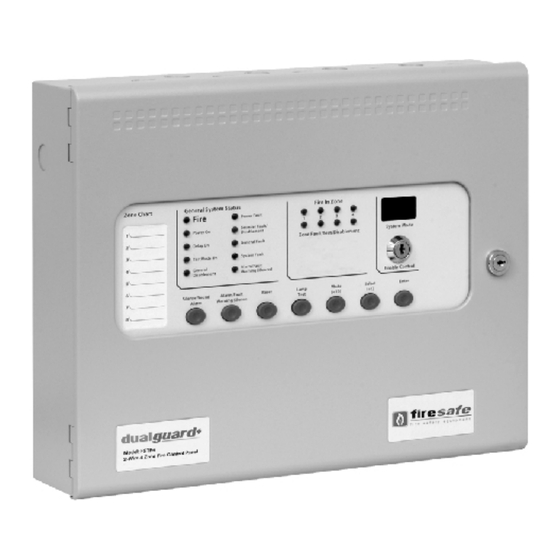
Page 6: 4B5. Control Panel Fascia
5. Control panel fascia In addition to the mandatory controls and indications required by the EN54-2 standard, two, seven segment, LED displays and MODE, SELECT and ENTER buttons are provided to allow easy entry and storage of codes to configure the control panel to suit the requirements of the installation. Removing the fascia Before the fascia can be removed it will be necessary to unplug the three way terminal block on the left hand side of the PCB. -
Page 7: 6B7. Software Revision Number
Wiring should enter the enclosure at the top of the panel using the knockouts provided and be formed tidily to the appropriate terminals leaving only enough wire to ensure that there is no strain on the PCB. Terminals are capable of accepting wires of up to 2.5mm Terminal designations Wiring must not go across the front of the circuit board plate or between the plate and the circuit board. -
Page 8: 8B9. Sounder Circuit Wiring
Polarised sounders must also be wired across the detection zone but in reverse polarity to that shown by the zone terminals (see figure below). At least one sounder should be fitted to each detection zone. Each zone can be configured individually as a 2-wire type zone or a non 2-wire type zone using configuration options C1 to C8. 9. -
Page 9: 10B11. Aux 24V Dc Supply
11. Aux 24V DC supply An auxiliary 24V DC supply is provided to enable local signalling or control of ancillary systems such as door release controllers. The terminals for the Aux 24V supply are labelled Aux 24V and ROV. The ROV terminal is the negative terminal and is the same terminal that should be used to switch the remote control terminals. -
Page 10: 13B14. Connection To Ancillary Boards
14. Connection to Ancillary boards Ancillary boards connect via a 2 core cable to the terminals marked RS485 + and – on the main control panel PCB. Up to 7 Ancillary boards may be connected and each board has terminals for the incoming cables and outgoing cables. -
Page 11: 15B16. Panel Operation
16. Panel operation 16.1 Normal condition Under normal conditions, control panels will have only the green, Power On LED lit. 16.2 Fire condition Upon receipt of a fire condition by activation of a detector or call point, the Common Fire indicator will light and the zonal Fire indicators will flash at around 2Hz. -
Page 12: 16B17. Configuration Options
16.10.3 Activate delays To activate delays on zones as set in configuration options 31 to 48, press the mode button until Ad appears on the seven segment LED display. When the enter button is pressed any zones that are set as delayed will have their alarm outputs delayed by the time set in configuration options 00 to 09. - Page 13 Table 8 – Configuration codes CODE FUNCTION COMMENTS SOUNDER DELAY TIME = 30 SECONDS Sets the time delay before sounders operate in combination with configuration codes 31 to 48 and access level 2 function AD. SOUNDER DELAY TIME = 1 MINUTE SOUNDER DELAY TIME = 2 MINUTES SOUNDER DELAY TIME = 3 MINUTES SOUNDER DELAY TIME = 4 MINUTES...
-
Page 14: 17B18. Watchdog Reset Switch
CODE FUNCTION COMMENTS ZONE 1 SHORT CIRCUIT INDICATES ALARM Changes the trigger threshold of the zone so that the control panel can be ZONE 2 SHORT CIRCUIT INDICATES ALARM used on older systems that had no short ZONE 3 SHORT CIRCUIT INDICATES ALARM circuit monitoring. -
Page 15: 18B19. Processor Reset Switch
19. Processor reset switch Once started, the microprocessor controlling the panel should continue to run continuously without interruption. If the microprocessor fails to run correctly it can be reset by pressing the PROCESSOR RESET button on the PCB inside the control panel. This should not normally be necessary but should be done as a matter of course if the system is behaving abnormally. -
Page 16: 20B21. Power Supply
21. Power supply The control panel requires a 230V (+10%/-15%), 50/60Hz, AC mains power supply which connects to the fused terminal block labelled “230V”. The fused terminal block contains a 20mm, F1.6A L250V fuse which should only be replaced with a similar type. The output voltage of the power supply is 28V DC +/- 2V and the total current rating including a maximum 0.7A for battery charging is 3 Amps. -
Page 17: B22. Maintenance
22. Maintenance Dualguard+ 2-wire control panels do not require any specific maintenance but should the control panel become dirty it can be wiped over with a damp cloth and should then be dried with a dry, lint free cloth. Detergents or solvents should not be used to clean the panel and care must be taken that water does not enter the enclosure. -
Page 18: 23B24. Record Of Configuration
24. Record of Configuration Use the table below to record the configuration codes that have been set on the control panel for future reference. Place a tick in the grey band for any configuration options that are set. It is recommended that a copy of this table is left with the control panel under the supervision of the person responsible for the fire detection system. - Page 19 CODE FUNCTION COMMENTS ZONE 1 SHORT CIRCUIT INDICATES ALARM Changes the trigger threshold of the zone so that the control panel can be used on older systems that had no short circuit monitoring. ZONE 2 SHORT CIRCUIT INDICATES ALARM ZONE 3 SHORT CIRCUIT INDICATES ALARM ZONE 4 SHORT CIRCUIT INDICATES ALARM ZONE 1 NON-LATCHING Renders the zone self-resetting so that it can be used to receive...
- Page 20 Man-1078FS4_Sigma_CP_User_firesafe 01 Page 20 of 22...
- Page 22 Man-1078FS4_Sigma_CP_User_firesafe 01 Page 22 of 22...
Need help?
Do you have a question about the dualguard+ FSTP4 and is the answer not in the manual?
Questions and answers