
Related Manuals for BW Trailers Tipper Eco Series


Summary of Contents for BW Trailers Tipper Eco Series
- Page 1 Translation of the Original Owner's Manual Tipper Eco series Operating instructions for all Tipper Eco series trailers with a weight class of 750kg to 1.500kg.
-
Page 2: Table Of Contents
Table of Contents Foreword ........................... 3 Identification ..........................3 Confirmation of conformity ......................4 Productnames ..........................4 Safety and warning instructions ....................5 Technical data .......................... 10 Nameplate / VIN number ......................10 Overview of trailer components....................12 Technical specifications ......................13 Optional equipment and accessories .................. -
Page 3: Foreword
Owner’s Manual must always accompany the trailer. Extra copies can always be obtained from a dealer or downloaded from our website. Identification This documentation was drawn up in Dutch by BW Trailers BV. Version designation: Operating instructions Tipper Eco series... -
Page 4: Confirmation Of Conformity
The trailer complies with the requirements of the European Directive 2007/46/EC for which the RDW has granted the necessary type approvals. Furthermore, the manufacturer BW Trailers BV confirms compliance with all relevant EC directives that apply to the hydraulically tipping part of the trailer in terms of health and safety. -
Page 5: Safety And Warning Instructions
Safety and warning instructions In order to recognise certain information in this manual more quickly and easily, text and images are indicated with certain symbols, signal words and highlighted text. Hazard warnings This instruction indicates an imminently hazardous situation which, if not avoided, may result in death or serious injury. - Page 6 Hazard symbols indicating particular sources of danger Warning of dangerous place! Risk of bruising! Be careful - several causes can lead to People's limbs such as hands / fingers / dangers for humans. feet can be bruised. Risk of bruising / knocks / Risk of chemical burns! of being hit! People can get burns through contact...
- Page 7 Prohibition Signs Unauthorised access is prohibited! Keep Do not spray with water! people at a distance! Prevent water jets from being sprayed Keep people away from the danger directly onto vulnerable parts of your zone. trailer. Entry area / zone prohibited! Never enter the danger zone / hazardous area during work.
- Page 8 General safety instructions The owner / operator must have read and understood the Owner’s Manual of the trailer thoroughly and completely. Ignoring the safety instructions and not following the steps during operations can lead to accidents involving personal injury. Improper operation can cause serious injury to yourself.
- Page 9 Intended use The trailer is intended for transporting general goods. The bucket of a tipper can tip backwards or backwards + sideways using a manually or (optionally) electrically controlled hydraulic tipping system. The trailer may only be operated by an adult, properly trained, in good physical condition. Foreseeable misuse The trailer is not suitable for: •...
-
Page 10: Technical Data
Technical data The technical data of your trailer can be found on: • The accompanying certificate of conformity • The nameplate • Type designation in the brochures and sales information on our website www.bwtrailers.be The loss of the EC certificate of conformity must be reported to the police. A duplicate of these documents can be requested from the manufacturer with official proof of loss. - Page 11 Example of type plate When contacting the manufacturer, you should always have the unique 17-digit VIN number to hand. On the basis of this number, the manufacturer can identify the trailer and request all linked specifications.
-
Page 12: Overview Of Trailer Components
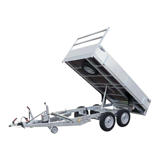
Overview of trailer components 1. Bucket 2. Chassis 3. V-drawbar 4. Coupling 5. Jockey wheel 6. Hydraulic group (operated manually) 7. Tipping cylinder 8. Power plug + holder 9. Breakaway cable (braked models) 10. Ladder carrier 11. Overrun brake (optional) 12. -
Page 13: Technical Specifications
Technical specifications KI-2500x1500 KI-3000x1500 Unladen weight 435 kg 490 kg Gross weight 1500 kg 1500 kg Loading capacity 1065 kg 1010 kg Number of axles Axle type AL-KO B-700-5 AL-KO B-700-5 Wheel brake 1637 1637 Overrun brake AL-KO 90S AL-KO 90S Coupling device AL-KO AK 161 AL-KO AK 161... -
Page 14: Optional Equipment And Accessories
Optional equipment and accessories Leaf rack 650mm Flat cover Frame + tarpaulin Pivotable Prop stands Integrated aluminum ramps Manual winch 7/13-pin adapter Wheel chock Anti-theft lock 1,5mm galva plate Aluminum Superstructure LED-lighting... -
Page 15: Electrical Installation
Electrical installation Connection 13-pole plug 13-pole plug Colour Function 1 / L Yellow Indicator left 2 / 54G Blue Fog light 3 / 31 White Mass Green Indicator right 4 / R 5 / 58R Brown Rear lights Wide-beam headlamps License plate light right 6 / 54 Break lights... -
Page 16: Before Setting Off
Faulty rear / contour lights, marker / outline lights Road users cannot see the vehicle clearly - danger of accidents! Before setting off, check that all the lights on the trailer are working properly. Before setting off • The driver of the towing vehicle must have a valid driving licence to drive the towing vehicle and the trailer. - Page 17 • If optional jockey wheel present - make sure the jockey wheel lock is securely fastened - turn the jockey wheel up and lift the coupling to a height greater than that of the tow ball. • Turn the towing vehicle backwards so that it is in line with the trailer and the coupling head is directly above the tow bar.
- Page 18 Swivelling capacity of the ball coupler Before setting off, check that the coupling of your vehicle allows the necessary swivelling in horizontal and vertical direction. Maintain a swivel range of vertical +/- 25° and horizontal +/- 20°.. Limited swivelling! Short tow bars with little freedom of movement for the ball coupler can limit the necessary turning movement during the ride.
- Page 19 Coupling height of ball coupler Before coupling your trailer for the first time, check that the height of the vehicle's ball head complies with the normalised height of 430 ± 35mm. The measured height must be within the range 395 - 465 mm between the road surface and centre ball head. If the measurement difference is too great, adjust the height of the vehicle's ball hitch.
-
Page 20: Loading And Unloading
Loading and unloading When loading a trailer, it is best to connect the trailer to the towing vehicle with the trailer's parking brake (braked trailer) engaged The user should place the load in the centre of the trailer and over the axles as much as possible. -
Page 21: Driving The Trailer
Driving the trailer When towing a trailer, the following steps must be taken to ensure that your vehicle / trailer is positioned on the road as safely as possible. • Before setting off, make sure that the ball coupler is fully engaged, that the auxiliary coupling cable (unbraked trailer) or break away cable (braked trailers) is connected, that the jockey wheel (if present) is fully retracted and locked and that the lights are all working. -
Page 22: Uncoupling
Uncoupling Open the coupling lever and lift the ball coupling of the tow bar ball from the towing vehicle. With higher ball pressures, lifting and lowering can be made easier by using a jockey wheel. Make sure an unbraked trailer is on a level surface. If this is not the case, use wheel chocks. Apply the parking brake (braked trailer) to prevent the uncoupled trailer from rolling away. -
Page 23: Ball Coupler Braked Trailers
Ball coupler braked trailers Ball coupler components for type AK161 / AK 301 / AK 351 1. Handle 2. Coupling lever 3. Semi-ball shaped cap 4. Key hole 5. Wear indicator 6. Locking indicator AK301 / AK351 AK161 Coupling operation Opening the ball coupler - for this purpose, pull the coupling lever up in the direction of the arrow. - Page 24 Driving without a correctly coupled ball coupler! The trailer can become disconnected from your vehicle's ball hitch during the journey and will sway and tilt. Wear indicator A wear indicator on the coupling lever indicates whether or not the wear limit of the tow ball of the towing vehicle or of the trailer coupling has been reached.
- Page 25 Breakaway cable braked trailers The breakaway cable activates an automatic braking process in case the trailer becomes disconnected while driving. When redirecting the breakaway cable, ensure that the loop is sufficiently long. This prevents the breakaway cable from being pulled in tight bends. Ways of attaching the breakaway cable Version 1: •...
- Page 26 Driving without or incorrectly installed breakaway cable! The trailer would not be secured in case of uncoupling and or the breakaway cable may come off while driving. The trailer brakes may not be activated, danger of accidents. Install the breakaway cable in such a way that negotiating bends is possible without any problems.
-
Page 27: Overrun Device With Parking Brake
Overrun device with parking brake Braked trailers have brakes with an overrun device that brakes the trailer fully automatically depending on the load. A parking brake serves to secure the trailer against rolling away and applies the brakes independently of the overrun device. Non-braked trailers have neither an overrun device nor a hand brake. - Page 28 AL-KO 251G AL-KO 2.8VB-1 AL-KO AE 3500 Danger of injury when parking the trailer! Until the full braking force is applied, the trailer can roll back 25-30 cm! When parking the trailer, ensure that there is sufficient distance. Releasing the parking brake when the trailer is not secured! The trailer can start moving uncontrollably and can hit/injure people.
-
Page 29: Wheels And Tyres
Wheels and tyres Wheels and tyres are important safety components on the trailer. They directly increase the driving comfort and improve the driving behaviour of the trailer. Visually inspect the wheels regularly and replace if: • cracks can be seen in the rim or tyre. •... - Page 30 Conversion bar / psi / kPa: • 1 psi = 0.0689 bar • 1 bar = 14.504 psi • 1 kPa = 0.01 bar The maximum tyre pressure applies to both empty and fully loaded trailers. Wheel bolts come undone! Wheels can come off while driving - danger of accidents! Tighten the wheel bolts alternately after the first 50 km and after each wheel change.
-
Page 31: Hydraulic Lift Function
Hydraulic lift function When using the tipping mechanism, observe the following instructions before starting the procedure: • The person operating the tipper has read and understood the instructions for operating the tipper. • No one should stand on or near the trailer while tipping, except the person with the relevant expertise to operate the tipper. - Page 32 Hydraulic lift function control 1. Turn the (optional) jockey wheel downwards. 2. Detach the load if it is still strapped in. 3. Open the tailgate of the bucket. 4. Unlock the upper frame of the undercarriage if applicable. 5. Tipping trailer with hand pump (standard equipment) a.
- Page 33 Hazard zones during tipping (*) models with optional electric operation Danger of crushing between chassis and loading floor! You can get trapped between the chassis and the loading floor if the floor support is not used correctly. Standing under an unsecured trailer! The trailer may start to move, slide off the lifting device and tilt - danger of crushing! Secure the trailer against rolling away by means of wheel blocks - place them under intact wheels.
-
Page 34: Cleaning
Cleaning The trailer can be cleaned with water. If you use a high-pressure cleaner, the following rules must be observed: • Distance to surface min. 70 cm • Water pressure max. 50 Bar • Water temperature max. 80 °C During cleaning, the electrical components must not come into contact with water. Do not clean the following parts directly with a high-pressure cleaner: •... -
Page 35: Storage / Parking
Aluminum parts Aluminium parts profiles (e.g. side panels) have an anodised coating, which offers optimal protection against corrosion. Storage / Parking If the trailer is not used for an extended period of time, the following storage instructions apply to avoid possible problems when the trailer is reused: •... -
Page 36: Troubleshooting
Troubleshooting Defect Cause Solution COUPLING Ball coupler does not click Ball cross-section greater than Ø 50 mm Have tow ball replaced into place after coupling Insufficient pressure on ball Push ball coupler down manually Inside of ball coupler dirty Clean and lubricate ball coupler ; replace if necessary. - Page 37 Defect Cause Solution BRAKES Insufficient braking Incorrect adjustment - excessive free Calibrate performance travel Braking lining not run-in Brake a few times Braking lining damaged - dirty Have brake shoe set replaced Excessive friction losses at draw bar Lubricate transmission devices, including brake cable Corrosion to the drawbar When reversing trailer is...
-
Page 38: Maintenance
Maintenance Trailers must be inspected by a competent / qualified specialist for their safe working order as and when required, but at least once a year in normal use (max. 10,000 km per year). If necessary, the service interval must be adapted to your usage routine and operating conditions. - Page 39 For safety reasons, all safety-relevant components must be regularly checked and maintained by qualified personnel. Damaged and non-functioning parts of the trailer must be replaced by original spare parts from BW Trailers BV. The accident prevention and environmental regulations must be observed during all maintenance work.
- Page 40 If the trailer is used permanently in mountainous areas, the trailer brake is exposed to greater wear. For commercial trailers, there is a risk that adjustments may have to be made earlier. Safety instructions for axles • AL-KO axles may not be welded. •...
- Page 41 The lubrication intervals must be adjusted according to the intensity of use and the degree of contamination Lubrication points for overrun device type AL-KO 90S / 161S/ 251S / 251G / 2.8VB type AL-KO AE3500 Lubrication points for ball couplings type AL-KO AK161 type AL-KO AK 301 / AK 351 Before lubricating...
- Page 42 Contaminated grease nipples. Contaminants can enter the bearing and lead to increased wear. Clean the grease nipples before lubricating. After lubricating Wipe away any excess grease or oil that has run out with a cloth. Check the parts are working properly. System failure due to faulty lubrication! Some parts must not be lubricated / greased under any circumstances.
-
Page 43: Service Intervals And History
First service 1.000 km service 5.000 km service Date Date Date Stamp BW Trailers - dealer Stamp BW Trailers - dealer Stamp BW Trailers - dealer Signature Signature Signature Inspection on delivery max. 6 months after purchase max. - Page 44 40.000 km service 45.000 km service 50.000 km service Date Date Date Stamp BW Trailers - dealer Stamp BW Trailers - dealer Stamp BW Trailers - dealer Signature Signature Signature max. 1 year after last service max. 1 year after last service max.
-
Page 45: Warranty And Liability
The report must also contain as detailed a description as possible of the defect, so that the recognised ▪ BW Trailers dealer and the manufacturer are able to respond adequately. If a defect is subsequently reported, the owner / user shall no longer be entitled to repair, replacement ▪...
Need help?
Do you have a question about the Tipper Eco Series and is the answer not in the manual?
Questions and answers