
Summary of Contents for Epiroc ContiLube II kit
- Page 1 90T, 100T, 120T, 135T, 140T, 150T, 155T, 165T, 180T Assembly instructions ContiLube® II kit © Construction Tools GmbH | 3390 7850 01 | 2023-05-05 Original Instructions...
-
Page 3: Table Of Contents
Contents Table of Contents 1 About these Assembly instructions .................. 4 2 Overview............................. 5 Equipment description............................ 5 Function................................ 5 3 Spare parts list........................... 6 EC 90T - ContiLube II kit ............................ 6 EC 100T - ContiLube II kit .......................... 8 EC 120T - ContiLube II kit .......................... 10 EC 135T - ContiLube II kit .......................... -
Page 4: About These Assembly Instructions
Assembly instructions 1 About these Assembly instructions These Assembly instructions describe how to retrofit a ContiLube ® II automatic lubrication system to your hy- draulic breaker. You are only allowed to retrofit the hydraulic breakers: • EC 90T • EC 100T • EC 120T •... -
Page 5: Overview
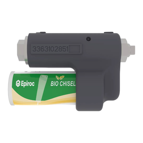
Assembly instructions 2.2 Function 2 Overview ContiLube II is a self-contained pump unit for delivering ® high-viscosity pastes such as those used for preference 2.1 Equipment description on hydraulic breakers. The pump is connected to the percussion unit by two hoses, one from port »PL«... -
Page 6: Spare Parts List
Assembly instructions 3 Spare parts list 3.1 EC 90T - ContiLube II kit 551 552 553 554 555 557 558 560 562 563 © Construction Tools GmbH | 3390 7850 01 | 2023-05-05 Original Instructions... - Page 7 Assembly instructions Description Remark Quantity Part number 550 (551-563) ContiLube II kit 3363 1178 05 ® 551 ContiLube II 3363 0671 23 ® 552 Pair of lock washers 3361 8505 96 553 Allen screw 3360 1037 50 554 Fitting 3363 0662 33 555 Hydraulic hose Grease line...
-
Page 8: Ec 100T - Contilube Ii Kit
Assembly instructions 3.2 EC 100T - ContiLube II kit 553 554 557 558 552, 553 © Construction Tools GmbH | 3390 7850 01 | 2023-05-05 Original Instructions... - Page 9 Assembly instructions Description Remark Quantity Part number 550 (551-563) ContiLube II kit 3363 1178 05 ® 551 ContiLube II 3363 0671 23 ® 552 Pair of lock washers 3361 8505 96 553 Allen screw 3360 1037 50 554 Fitting 3363 0662 33 555 Hydraulic hose Grease line...
-
Page 10: Ec 120T - Contilube Ii Kit
Assembly instructions 3.3 EC 120T - ContiLube II kit 553 554 555 557 558 560 552, 553 © Construction Tools GmbH | 3390 7850 01 | 2023-05-05 Original Instructions... - Page 11 Assembly instructions Description Remark Quantity Part number 550 (551-563) ContiLube II kit 3363 1178 05 ® 551 ContiLube II 3363 0671 23 ® 552 Pair of lock washers 3361 8505 96 553 Allen screw 3360 1037 50 554 Fitting 3363 0662 33 555 Hydraulic hose Grease line...
-
Page 12: Ec 135T - Contilube Ii Kit
Assembly instructions 3.4 EC 135T - ContiLube II kit 553 554 557 558 552, 553 © Construction Tools GmbH | 3390 7850 01 | 2023-05-05 Original Instructions... - Page 13 Assembly instructions Description Remark Quantity Part number 550 (551-563) ContiLube II kit 3363 1178 05 ® 551 ContiLube II 3363 0671 23 ® 552 Pair of lock washers 3361 8505 96 553 Allen screw 3360 1037 50 554 Fitting 3363 0662 33 555 Hydraulic hose Grease line...
-
Page 14: Ec 140T - Contilube Ii Kit
Assembly instructions 3.5 EC 140T - ContiLube II kit 551 552 555 557 © Construction Tools GmbH | 3390 7850 01 | 2023-05-05 Original Instructions... - Page 15 Assembly instructions Description Remark Quantity Part number 550 (551-563) ContiLube II kit 3363 1178 05 ® 551 ContiLube II 3363 0671 23 ® 552 Pair of lock washers 3361 8505 96 553 Allen screw 3360 1037 50 554 Fitting 3363 0662 33 555 Hydraulic hose Grease line...
-
Page 16: Ec 150T - Contilube Ii Kit
Assembly instructions 3.6 EC 150T - ContiLube II kit 552 553 554 555 557 558 © Construction Tools GmbH | 3390 7850 01 | 2023-05-05 Original Instructions... - Page 17 Assembly instructions Description Remark Quantity Part number 550 (551-563) ContiLube II kit 3363 1178 05 ® 551 ContiLube II 3363 0671 23 ® 552 Pair of lock washers 3361 8505 96 553 Allen screw 3360 1037 50 554 Fitting 3363 0662 33 555 Hydraulic hose Grease line...
-
Page 18: Ec 155T - Contilube Ii Kit
Assembly instructions 3.7 EC 155T - ContiLube II kit 553 554 555 557 © Construction Tools GmbH | 3390 7850 01 | 2023-05-05 Original Instructions... - Page 19 Assembly instructions Description Remark Quantity Part number 550 (551-563) ContiLube II kit 3363 1178 05 ® 551 ContiLube II 3363 0671 23 ® 552 Pair of lock washers 3361 8505 96 553 Allen screw 3360 1037 50 554 Fitting 3363 0662 33 555 Hydraulic hose Grease line...
-
Page 20: Ec 165T - Contilube Ii Kit
Assembly instructions 3.8 EC 165T - ContiLube II kit 551 552 553 554 555 557 558 560 562 563 © Construction Tools GmbH | 3390 7850 01 | 2023-05-05 Original Instructions... - Page 21 Assembly instructions Description Remark Quantity Part number 550 (551-563) ContiLube II kit 3363 1178 05 ® 551 ContiLube II 3363 0671 23 ® 552 Pair of lock washers 3361 8505 96 553 Allen screw 3360 1037 50 554 Fitting 3363 0662 33 555 Hydraulic hose Grease line...
-
Page 22: Ec 180T - Contilube Ii Kit
Assembly instructions 3.9 EC 180T - ContiLube II kit © Construction Tools GmbH | 3390 7850 01 | 2023-05-05 Original Instructions... - Page 23 Assembly instructions Description Remark Quantity Part number 550 (551-563) ContiLube II kit 3363 1178 05 ® 551 ContiLube II 3363 0671 23 ® 552 Pair of lock washers 3361 8505 96 553 Allen screw 3360 1037 50 554 Fitting 3363 0662 33 555 Hydraulic hose Grease line...
-
Page 24: Tightening Torques
Assembly instructions 4 Tightening torques 4.1 EC 90T - EC 135T Description Tightening torque Remark Allen screw 85 Nm (63 ft lbs) Allen key secure all 4 Allen screws with Loctite 243 size 10 screwed in the ContiLube ® II Fitting 45 Nm (33 ft lbs) Open-ended wrench Loctite 243 size 17, 19, 22... -
Page 25: Assembly
Assembly instructions 5 Assembly WARNING Hydraulic oil spills Spilt hydraulic oil can make a floor slippery. If people slip n Wear your personal protective equipment described they can be injured. Hydraulic oil is environmentally in the Safety and operating instructions of the hy- harmful and must not penetrate the ground or enter the draulic breaker (see chapter Safety instructions). - Page 26 Assembly instructions 2. The hydraulic breaker must be connected to the hy- If the hydraulic breaker is fitted with a high-pressure ac- cumulator, it can take longer to relieve the pressure in draulic system of the carrier, i.e. the hydraulic hoses the hydraulic system to the tank, since a larger volume must be connected up and the respective shut-off of oil has to be drained away.
-
Page 27: Assembly Instructions Ec 140T, Ec 150T
Assembly instructions 15. Connect oil line (558) to the fitting (562) port»PL«. 5.2 Assembly instructions Tighten oil line (558) to the torque required (see EC 140T, EC 150T chapter Tightening torques). 16. Route grease line (555) and oil line (558) as shown n Before assembling the ContiLube II you must de- ®... -
Page 28: Assembly Instructions Ec 155T - Ec 180T
Assembly instructions 13. Make a hole in each plug (E). 7. Tighten fitting (554) to port »L« of ContiLube ® II (551) to the torque required (see chapter Tightening 14. Push grease line (555) and oil line (558) through the torques). -
Page 29: Operation
Assembly instructions 6.2 ContiLube® II operation 6 Operation Please remember the following: n Wear your personal protective equipment described • The ContiLube II (C) is self-venting, i.e. the system ® in the Safety and operating instructions of the hy- does not require you to vent it. draulic breaker (see chapter Safety instructions). -
Page 30: Adjustment
Assembly instructions 6.3 Adjustment The factory setting is 18.6 mm (0.72 in.) (x). n When starting up the unit set the delivery rate so that the working tool receives adequate lubrication. This will depend both on the kind of grease used and the job involved. -
Page 31: Troubleshooting
No pump delivery; no pressurised Check branch line from hydraulic breaker supply line. Carrier driver oil supply Check hydraulic system. Workshop or Epiroc No pressure relief in the pump af- Customer Center / ter hydraulic breaker is switched Business partner in... -
Page 32: Technical Specifications
Assembly instructions 8 Technical specifications Type ContiLube ® II Service weight 5.4 kg (12 lbs) Dimensions with grease cartridge Height 84.5 mm (3.33 in) Width 193 mm (7.60 in) Length 305 mm (12.00 in) Operating pressure, min. 100 bar (1450 psi) Delivery 0.02 - 0.84 g/stroke Inside thread on pump body ... - Page 36 Any unauthorized use or copying of the contents or any part thereof is prohibited. This applies in particular to trademarks, model denominations, part numbers, and drawings. epiroc.com...
Need help?
Do you have a question about the ContiLube II kit and is the answer not in the manual?
Questions and answers