Advertisement
Quick Links
Tel. Chelmsford
62 442
TX 99 338
; n-Fi
M
W
/LW
y SW
Y, EFM
Technical Service Organization
Waterhouse
Lane, Chelmsford,
Essex.
:
Tel. 0245-54621
TX 99338
2200 Borgerhout
Belgium
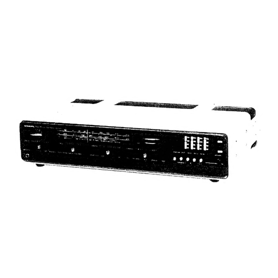
MODEL
TFS-
70
Prins-Leopold-Straat
28
Tel. 03/361045
TxX32508
03/357670
Switzerland:
TRANSACO
AG
Kanzleistrasse
126 8004
Zurich
Tel. 39 45 60/23
50 40
TX
52 3262
When
transistors
Q711,
712,
713,
714
are exchanged,
the
following adjustment
is necessary:
1-1
Measuring Equipment
(a) Current Meter
1-2
Condition
of the Set
e:
P
ine
is
2
Upper
Cabinet
ay Ping Boat
a: ee
Punetung
Koad Bx4
|
(p=
—,
(
d
B x
f
Bove
oN
a
a
Secs
(a) Treble... ......02.
Middle Position
(i) Bass
2.4) oo dat Sore Snes Middle Position
(c) Volume
..........
Minimum
(d)Balance
..........
Middle Position
(e) Muting, AFC, Loudness, Tape, Low, High
........
Stopper Plate Crd
OFF
Position
(f) ST/MONO......... ST
vere
te
ee
(g) Mode
............
AUX
(ak Cabin -
(h) Speaker... 2.0.00...
A
A QUA
6 oc
ea
Gee ade: 3 ST
=
1-3
Adjustment
Stepner
(a) Adjust VR701, VR702 to middle position.
Diseases
=
:
(b) Connect
the Current Meter
@ Side to Terminal 3(Rch.)
Pater
ee
oo
e e
or 4(Lch.) on the Fuse Board A, and the Current Meter
oe
ae
c
© Side to Terminal 1(R ch) or 2(L ch).
(c) Adjust VR702
to 40 mA
£3 mA.
<i
aa
(dj Set the Current Meter to L Channel.
pee
(e) Adjust VR701 to 40 mA +3 mA.
Figure 1
(f) Repeat Procedure a - d several times.
CABINET
REMOVAL
2,
AM
IF Adjustment
;
:
2-1
Measuring
Equipments
Remove six screws on the cabinet sides.
,
(a) AM Standard Signal Generator
Remove
two screws
on the cabinet
rear.
Pull backward the upper cabinet, then this will be removed.
(b) Audio Oscillator
ADJUSTMENT
INSTRUCTIONS
2-2
Preparation of Adjustment
(a) Volume:
Max., Mode:
MW, Others: same as procedure
1-2
(b) Measuring Connection is as follows:
FwWN
>
Audio-Osc.
(3kHz) Out s
AM
_IF Board
Terminal
Standard
sa,
Soe!
Signal
Generator
:
Dummy
toad
Oscilloscope
EXT
10K
9.01
O
QO
@
w—tt
>
a
Figure 3
2-3
Adjustment
(a) Set S.G. to 465
KHz
(Mod. 400 Hz 30%) 80 dB, and
adjust IF cores of T401, T402, T403 and T404 for maxi-
mum
output reading.
Adjust the Attennator
of S.G. according to increase the
Output,
and
put the output
reading
to 500
mW
(2¥V)
Figure 2
appro
Advertisement


Need help?
Do you have a question about the TFS-70 and is the answer not in the manual?
Questions and answers