Advertisement
Quick Links
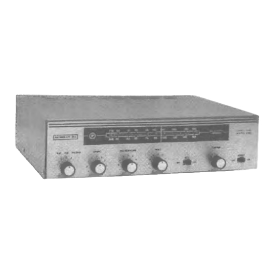
OPERATING INSTRUCTIONS
MODEL 870-15A AM-FM RECEIVER
WARNING: TO PREVENT FIRE OR SHOCK HAZARD, DO NOT EXPOSE THIS RECEIVER TO RAIN OR MOISTURE.
DESCRIPTION
The
Raymer
Model
870-15A
is an
all solid state
monaural AM-FM background music receiver with pro-
visions for paging. The receiver consists of a tuner for
the 88-108 MHz FM band, the 550-1650 KHz AM band
and a 15 Watt RMS audio amplifier with a microphone
preamplifier.
The receiver has a music output and a preamp output
jack for connection to an external amplifier as well as a
high level phono
input jack and a microphone
jack
which
may
be switched
for either high or low im-
pedance input. The speaker outputs of the receiver are
for 4 or 8 ohm; or 25 volt or 70 volt balanced lines.
The Model 870-15A also features an electronic music
mute (precedence) circuit in place of a relay to quickly
fade out the music while paging; after paging the music
is smoothly restored. The receiver also has a variable
tone control.
UNPACKING
The unit is to be removed carefully from the carton
and inspected for any possible damage
in transit. If
there is any evidence of any damage which might have
occurred in shipment, immediately notify your supplier,
or
the
transportation
company
which
delivered
it.
Claims for damage sustained in transit must be made
upon
the carrier.
Save
all packing
material
for in-
spection by the claim agent who will furnish you with
the proper forms and will also give you the necessary
instructions for filing a claim.
INSTALLATION
This unit has an AC line cord with a 3 prong plug.
The line cord should be plugged into a 3 wire grounded
105 to 120 volt 60Hz AC outlet. This will also ground
the receiver.
The AC
receptacle on the rear panel is a 3 wire
grounded outlet which can supply power to accessory
or auxiliary equipment. Any auxiliary equipment con-
nected
to this AC
receptacle
is controlled
by the
POWER on-off switch so that turning off the power on
the unit turns off all equipment.
CONNECTIONS
All connections are made on the rear panel of the
unit.
INPUT CONNECTIONS
All patch cords and input leads other than Music
Mute must be shielded cables. The Music Mute ieads
do not have to be shielded. When output leads are run
near an unshielded microphone input plug, or when run
together
with
the microphone
precedence
leads, a
supersonic
oscillation
may
occur.
When
this does
occur, it will appear as a distortion in the amplifier
output, and oftentimes will cause the circuit breaker to
The Microphone input jack is for an unbalanced line
only. If it is necessary to use a balanced input, an out-
board
matching
transformer
such
as Raymer
Model
LMT-150 must be used. If the signal source is a tele-
phone line or a 500 ohm input, the connection can be
made
to the amplifier by means
of a Raymer Tele-
phone Matching Adaptor TM-1
or TM-2. The switch
above the microphone input selects the proper input
impedance. The Hi-Z position will match either crystal
or high impedance
dynamic
microphones;
the Lo-Z
position will match microphones in the 150 to 500 ohm
range.
CAUTION
To
avoid
possible
supersonic
oscillation
which
might result in damage to the unit, it is mandatory
that a shielded (metal cover) microphone plug be
used.
Advertisement


Need help?
Do you have a question about the 870-15A and is the answer not in the manual?
Questions and answers