Table of Contents

Related Manuals for CYG Powermate A3.68

Summary of Contents for CYG Powermate A3.68
- Page 1 Powermate A3.68/A4.6/A5/A6 Lite Residential ESS User Manual Ver 1.6 CYG SUNRI CO., LTD. December 2022 The Manual is applicable to Powermate A3.68/A4.6/A5/A6 Hybrid Inverter and is compatible with V1.1 and its compatible version programs.
- Page 2 This Manual is compiled and published by CYG SUNRI CO., LTD. Therefore, we reserve the right to the final interpretation of related products. We are sincerely sorry for that related products subsequently upgraded may be slightly different from those in the instruction manual and the manual may be upgraded without prior notice.
-
Page 3: Table Of Contents
Contents 1 SAFETY..................................1 1.1 S ............................... 1 YMBOLS 1.2 S .............................. 1 AFETY RECAUTION 2 INTRODUCTION..............................3 2.1 P .................................. 3 REFACE 2.2 S ............................3 YSTEM NTRODUCTION 2.3 P P3.68/P4.6/P5/P6 H ....................4 OWERMATE YBRID NVERTER 2.3.1 Product Overview..............................4 2.3.2 Product Appearance............................. 5 2.3.3 Specification................................ - Page 4 3.8.1 Danger................................19 3.8.2 Warning................................19 3.8.3 Caution................................20 3.9 P ................................20 ARTS 3.10 S ............................21 YSTEM PPEARANCE 3.11 L ............................21 IABILITY IMITATION 4 INSTALLATION..............................22 4.1 I ....................... 22 NSTALLATION SITE AND ENVIRONMENT 4.1.1 General................................22 4.1.2 Restricted Locations............................23 4.1.3 Installation Environment...........................
-
Page 5: Safety
1 Safety Before using the Powermate Residential ESS , please read all instructions and cautionary markings on the unit and manual. Put the instructions where you can take them easily. The ESS inverter of ours strictly conforms to related safety rules in design and test. Local safety regulations shall be followed during installation, operation and maintenance. - Page 6 To avoid electric shock, DC input and AC output of the Powermate hybrid inverter must be terminated at least 5 minutes before performing any installation or maintenance. The temperature of some parts of the Powermate hybrid inverter may exceed 60℃ during operation. Do not touch the inverter during operation to avoid being burnt.
-
Page 7: Introduction
2 Introduction 2.1 Preface This manual will provide the users who use the Powermate Series of CYG Sunri Co., Ltd. (SH. 600525) (Short for CYG Energy as below) with the detailed product information and the installation instructions. Please read this manual carefully and put this manual on some place where is convenient to installation, operation, obtain. -
Page 8: Powermate P3.68/P4.6/P5/P6 Hybrid Inverter
2.3 Powermate P3.68/P4.6/P5/P6 Hybrid Inverter 2.3.1 Product Overview The Powermate P3.68/P4.6/P5/P6 hybrid inverters are high-quality inverter which can convert solar energy to AC energy and store energy into battery. The inverter can be used to optimize self-consumption, store in the battery for future use or feed into public grid. -
Page 9: Product Appearance
2.3.2 Product Appearance... -
Page 10: Specification
2.3.3 Specification Model Powermate P3.68/120 Powermate P4.6/120 Powermate P5/120 Powermate P6/120 Efficiency Max.efficiency (PV to AC) 96.00% 97.30% Max.efficiency (BAT to AC) 93.50% 94.00% Input( PV) Max PV power 4500W 9000W Max PV voltage 550V Max input current (input A/input 15A/15A Max short current (input A/input 20A/20A... -
Page 11: Powermate Pack5.1 Bess
2.4.1 Product Overview Powermate Pack5.1 is a lithium iron phosphate battery pack (including BMS) designed and manufactured by CYG. It is composed of 16 series of cells. This product is suitable for load equipment with working current less than 100A. - Page 12 Product Type Powermate Pack5.1 Cell Technology Li-ion(LFP) Capacity(kWh) 5.12 Voltage(Vdc) 51.2 Capacity(AH) Battery Module Cell Series Quantity(pcs) Charge Upper-Voltage(Vdc) 56.2 Charge Current(Amps.Normal) Charge Current(Amps.Max) Discharge lower-Voltage(Vdc) 45.6 Discharge Current(Amps.Normal) Discharge Current(Amps.Max.) Depth of Discharge(%) Dimension(W*D*H,mm) 515*200*400 Communication RS232/RS485\CAN Protection Class IP54 Weight (kg) 46.6...
-
Page 13: Button And Port
2.4.3 Button and Port 2.4.3.1 ON/OFF For multiple Powermate Pack5.1 in parallel, long press (more than 3 seconds) ON/OFF button of MASTER battery (Which connect with inverter), normal LED will be lighted, battery system will automatically encode and assign ID to each slave battery, then battery system will operate normally. Press ON/OFF button of Master PACK (which connect with inverter) more than 3s, LED will flash in the front panel and then release the button, the master pack will shut down after all slave packs shut down (Sleep mode). -
Page 14: System Box Information
flash 1 0.25slight//3.75soff flash 2 - 0.5s light /0.5soff flash 3 - 0.5s light /1.5soff LED Indicators Instructions ON/OFF Normal Fault Power indicator LED Status Normal/Alarm/Protection Descriptions Shut down dormancy All OFF Indicates Normal Light Flash 1 Standby Standby According to the power indicator The module Alarm Light... -
Page 15: Self Used Mode
3.1 Self Used Mode Under Self Used mode, the priority of PV energy will be Load > Battery > Grid, that means the energy produced by PV gives priority to local loads, excess energy is used for charging the battery, and the remaining energy is fed into the grid. -
Page 16: No Pv Input
3.1.3 No PV Input The inverter will first discharge the battery energy for home load consuming when no PV input( such as in the evening or some cloudy or rainy days). If the demand is not met then will consume the grid energy. 3.2 Feed-in Priority Mode Under this mode, the priority of PV energy will be Load >... -
Page 17: Limited Pv Power
3.2.2 Limited PV power When PV energy is limited and cannot meet the feed-in grid power, the battery will discharge to meet it. 3.2.3 No PV Input The inverter will first discharge the battery energy for home load consuming when no PV input ( such as in the evening or some cloudy or rainy days). -
Page 18: Time-Based Control Mode
3.3 Time-Based Control Mode Under this mode, you can control the charging and discharging of the inverter. You can set the following parameters based on your requirements: - Charge and discharge frequency: one time or daily - Charging start time: 0 to 24 hours - Charging end time: 0 to 24 hours - Discharge start time: 0 to 24 hours - Discharge end time: 0 to 24 hours... -
Page 19: Allow Ac Charging: Wealthy Pv Power
3.4.1.2 Forbid AC charging:Limited PV power When PV energy is limited, PV gives priority to charging the battery, and the grid directly meet the load demand. Allow AC charging In this situation, the battery can be charged both with PV and AC 3.4.2 Allow AC charging: Wealthy PV power When PV energy is wealthy, PV charges the battery first, then meets the load, and the rest is fed into the grid. -
Page 20: Off Grid Mode
3.5 Off Grid Mode When the power grid is cut off, the system automatically switches to Off Grid mode. Under off-grid mode, only critical loads are supplied to ensure that important loads continue to work without power failure. Under this mode, the inverter can’t work without the battery 3.5.1 Wealthy PV Energy When PV energy is wealthy, the PV power will be first consumed by critical load, charges battery then smart load. -
Page 21: Limited Pv Power
3.6 Safety Introduction 3.6.1 Manual Keeping This manual is under the copyright of CYG SUNRI CO., LTD. with all rights reserved. Please keep the manual properly and operate in strict accordance with all safety and operating instructions in this manual. -
Page 22: Operator Requirements
3.6.2 Operator Requirements Operators should have professional qualifications or training. Be familiar with the entire storage system, including its components and working principles. Operators should be familiar with the Product Manual. During maintenance, do not operate any device until all devices are shut down and discharged completely. 3.6.3 Setting of Warning Sign for Safety During instruction, maintenance, and repair, follow the following instructions to prevent misuse or accidents caused by non-professionals:... -
Page 23: General Precautions
explosion and chemical danger of leakage of dangerous substances. However, the gas release port will be operated if the product is subjected to fire, increases mechanical shock, decomposes, and misuse increases electrical stress. The battery case will be pushed to the limit. Harmful substances may be released. In addition, if the surrounding fire heats strongly, it may produce a pungent or harmful smoke emission. -
Page 24: Caution
You must carry an ABC certified fire extinguisher with a minimum capacity of 2kg. Smoking is strictly prohibited in the vehicle and near the vehicle while loading and unloading. When replacing the battery module, if the dangerous goods package needs to be changed, please ask the supplier to change the dangerous goods package and take delivery of the goods by himself. -
Page 25: System Appearance
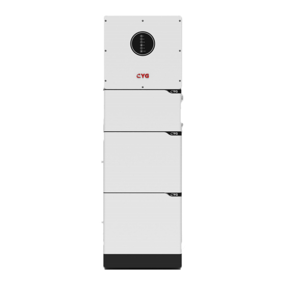
3.10 System Appearance Object Description Hybrid Inverter System box PACK 1(Battery 1) PACK 2(Battery 2) 3.11 Liability Limitation It does not assume any direct or indirect responsibility for any product damage or property damage caused by... -
Page 26: Installation
the following circumstances. Modifying or changing the design or replacing parts without authorization; Changing, repairing and erasing serial numbers or seals by non-professional technicians; System design and installation does not meet standards and regulations; Failure to comply with local safety regulations (VDE is DE, SAA is AU) ; Transportation damage (including paint scratches caused by internal friction of packaging during transportation). -
Page 27: Restricted Locations
• places with flammable materials or gases or an explosive atmosphere. 4.1.2 Restricted Locations The Powermate ESS shall not be installed— (a) in restricted locations as defined for panels in AS/ NZS 3000; (b) within 600 mm of any heat source, such as hot water unit, gas heater, air conditioning unit or any other appliance. - Page 28 4.2.1 Step 1 Take out the base from system box and placed the base against the wall, the distance between the base and the wall is 30mm as follows. Use the gradienter to keep the base is not aclinic. 4.2.2 Step 2 Installation of the first Battery PACK: Place the first Battery PACK on top of the base.
- Page 29 Schematic diagram of two PACKs installed 4.2.4 Step 4 Install the L-shaped bracket and move the PACK to attach the L-shaped bracket to the wall 4.2.5 Step 5 Drill holes for the inverter wall bracket. First, lock the lower end of the inverter wall bracket with two m5 flange nuts, and then use a marker pen to trace the position of the fixing holes between the inverter wall bracket and the wall and the position of the L-shaped bracket and the wall.
- Page 30 4.2.7 Step 7 Install the junction box and lock the junction box to the PACK with 4 pieces of M5X10 cross outer hexagon, as shown in the figure below: 4.2.8 Step 8 Install the inverter according to the method shown in the figure below. When the front panel of the inverter is flush with the junction box below, tighten the screws between the inverter and the bracket..
-
Page 31: Electrical Connection
5 Electrical Connection This chapter shows the details connection of Powermate ESS . And PV connection is N/A for Powermate hybrid inverters. The following illustration only uses the Powermate series hybrid inverters as an example. Powermate system connection diagram: A protective earth (PE) terminal is equipped at the side of the inverter. Please be sure to connect this PE terminal to the PE bar for reliable grounding. -
Page 32: Battery Power And Communication Cable Connection
5.2 Battery power and communication cable connection Connect the battery power cable in the down side of the breaker in the system box to the upper battery which is the master battery. Connect the battery power cable in the up side of the breaker in the system box to the inverter battery ports. -
Page 33: Grid/Eps Connection
5.3 Grid/EPS Connection Grid/EPS connection please refer to below. An AC breaker should be installed between inverter and the grid/EPS. 1.Before connecting the AC cable from inverter to AC breaker, you should confirm the AC breaker is working... -
Page 34: Pv Connection (N/Afor Ac Couple Inverter ) Pv Connection
normally. Turn off the AC breaker and keep it open. 2.Connect the PE conductor to grounding electrode, and connect the N and L conductors to AC breaker. 3.Connect the AC breakers to the grid/EPS grid. Multiple inverters cannot share a circuit breaker. No load is allowed between the inverter and the AC circuit breaker. -
Page 35: Ct Connection
Please refer to the meter instruction manual for details. 5.5.1 CT Connection Before connecting to Grid, please install a separate AC breaker (≥60A; not equipped) between CT and Grid. This ensure the inverter can be security disconnected during maintenance. The connection diagram of power cable of CT is as shown in the figure below: Please attention to the Current interchanger (CT) connection. - Page 36 DRMs Connection DRMs is a shortened form for “inverter demand response modes”. It is a compulsory requirements for inverters in Australia.
-
Page 37: Meter/Ct Connection
5.5.3 Meter/CT Connection RJ45 Terminal Configuration of Meter/CT Communication Function RS485_A Description RS485_BRS485_ARS485_BCT+ Meter Connection Inverter Meter Pin1 Pin24 Pin3(RS485_A ) Pin2 Pin25 Pin4(RS485_B ) Connect meter. Refer to the following steps:... -
Page 38: Ct Connection
CT Connection RS485 Connection RJ45 Terminal Configuration of RS485 Communication... -
Page 39: Ntc/Rmo/Dry Connection(S)
5.5.4 NTC/RMO/DRY Connection(s) 9-Pins Terminal Configuration of Auxiliary Communication Pin123456789 Function Description NO1 (Normal Open) NC1 (Normal Close) NC2 (Normal Close) NC2 (Normal Close) REMO OFF GND S (NTC BAT) NTC BAT+... -
Page 40: Gprs/Wifi Module Connection (Optional) Gprs/Wifi Module
Insert its 9-Pins terminal into the corresponding NTC/RMO/DRY port on the ESS inverter. Install the seal into the threaded sleeve, fasten the rubber nut and screw the waterproof cover back to inverter firmly with 4 x M4 screws; 1.2N.m. 5.5.5 GPRS/WiFi Module Connection (Optional) GPRS/WiFi module 6 Startup/Shutdown the System Before operation, you need to Check: 6.1 Startup the System... -
Page 41: Shutdown The System
AC Frequency 50/60Hz PV Voltage 90~530V BatteryVoltage42~60V GridACVoltage180~270V Make sure all the above aspects are right, then follow the procedure to start up the inverter: 6.2 Shutdown the System According to actual situation, if have to shut-down the running system, please follow below procedure: Unpower off the battery. -
Page 42: App Commissioning
7 APP Commissioning Download the mobile APP What can it do? Local monitoring and debugging through short distance wireless communication Remote monitoring the PV inverter from anywhere as long as your smart mobile device connected to the internet How to download it? ... -
Page 43: App Local Settings
a. Login App with your cloud account. Click “ + ” and select a PlantType to add the power station. b. Enter power station information then click CONFIRM. c. Select the power station you added, go to List page, and click “ + ” to scan the serial number barcode at the safety label on the machineto add inverter. - Page 44 5. Go to Quick Setup page, and enter the WIFI SSID and password of the current network environment according to the following instructions. And then the inyerter is connected to the Internet. 6. Login as adminstrator Go to Console > Access Management > Change User page, and enter the adminstrator password to login as adminstrator.
Need help?
Do you have a question about the Powermate A3.68 and is the answer not in the manual?
Questions and answers