Table of Contents
Advertisement
Quick Links
AirGate-Modbus
INSTRUCTIONS MANUAL V1.0x C
FCC
This equipment has been tested and found to comply with the limits for a Class A digital device, pursuant to Part 15 of the FCC Rules. These limits
are designed to provide reasonable protection against harmful interference when the equipment is operated in a commercial environment. This
equipment generates, uses, and can radiate radio frequency energy and, if not installed and used in accordance with the instruction manual, may
cause harmful interference to radio communications.
Any changes or modifications not expressly approved by the party responsible for compliance could void the user's authority to operate this
equipment.
RF Exposure: A distance of 20 cm shall be maintained between the antenna and users, and the transmitter module may not be co-located with any
other transmitter or antenna.
CE Mark
This is a Class A product. In a domestic environment, this product may cause radio interference in which case the user may be required to take
adequate measures.
ANATEL
This device does not provide protection against harmful interference, and may not cause interference in a properly authorized system.
For more information, see ANATEL's website: www.anatel.gov.br.
NOVUS AUTOMATION
1/27
Advertisement
Table of Contents

Related Manuals for Novus AirGate-Modbus

Summary of Contents for Novus AirGate-Modbus
- Page 1 AirGate-Modbus INSTRUCTIONS MANUAL V1.0x C This equipment has been tested and found to comply with the limits for a Class A digital device, pursuant to Part 15 of the FCC Rules. These limits are designed to provide reasonable protection against harmful interference when the equipment is operated in a commercial environment. This equipment generates, uses, and can radiate radio frequency energy and, if not installed and used in accordance with the instruction manual, may cause harmful interference to radio communications.
-
Page 2: Table Of Contents
7. SOFTWARE SETUP .......................................10 8. CONFIGURATION MODE .......................................11 9. DETERMINATION AND SELECTION OF THE SERIAL PORT (COM) - WINDOWS ....................12 10. CONFIGURATIONS - AIRGATE-MODBUS ................................14 11. DATA COMMUNICATION - SERIAL ..................................16 12. DATA COMMUNICATION (WIRELESS) .................................17 13. MODBUS COMMANDS ......................................18 14. -
Page 3: Introduction
1. INTRODUCTION AirGate-Modbus is a device with a link interface function between a network with Modbus RTU protocol about RS485 and a wireless network with proprietary protocol about IEEE 802.15.4. Resulting from an advanced technological development, the device stands out in many aspects, such as high performance, high connectivity and easy setup and operation. -
Page 4: Connection And Installation
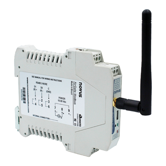
Fig. 3 shows the electrical connections needed. Terminals 1, 2 and 3 are destined for the communication with Modbus network. These terminals are internally connected to terminals 4, 5 and 6. The terminals 7, 8 and 9 are used for AirGate-Modbus power supply. -
Page 5: Operation
Fig. 4. Fig. 4 - AirGate-Modbus frontal panel 3.1. The USB interface of AirGate-Modbus is used for setup. Depending on the operation mode set, this interface can be connected to a PC functioning as master of the Modbus RTU network. 3.2. -
Page 6: Operation Modes
Multiplexing of the USB and RS485 for IEEE 802.15.4 In this mode, AirGate-Modbus uses the RS485 and USB interfaces for the multiplexing of Modbus masters. The masters must be directly linked to these interfaces. The wireless interface is used to communicate with other AirGate-Modbus devices in RS485-Slaves operation mode. -
Page 7: Using The Operation Modes
Division of a wired network in wired segments interconnected by wireless segments. Wireless segments located close to the Modbus master which communicates by USB port. It allows the AirGate-Modbus using as a USB-RS485 convertor for the first wired segment. Fig. 6 illustrates this possible application: Fig. -
Page 8: Long Reach Application
In seeking to expand the network and in order to obtain a greater distance, it is possible to assemble a tree shaped topology. As exemplified in Fig. to expand the network, an AirGate-Modbus configured as a RS485-Slaves (Firmware > 1.23) was inserted with the same PAN ID (5670). In another segment, two AirGates were assembled using the RS485 interfaces, an AirGate-Modbus operating the RS485-Slaves mode and an AirGate-Modbus operating in RS485-Master mode. - Page 9 In case there is the need to implement a tree-shaped network, a restriction must be observed. Due to issues imposed by Modbus standard, Modbus slaves must not be connected between AirGate-Modbus as signed in Fig. 9: Fig. 9 - Restriction...
-
Page 10: Software Setup
The DigiConfig application is a Windows® program used for the AirGate-Modbus configuration. For its installation, execute the file "DigiConfigSetup.exe". When installing the setup software, the USB Serial Port driver of AirGate-Modbus may be automatically installed, as shown in Fig. 10: Fig. -
Page 11: Configuration Mode
Fig. 12 – DigiConfig main screen To edit the configurations of the AirGate-Modbus, after clicking the Search button, you must select it in the tree to the left of the main screen. To quit setup mode, you must press the SETUP BUTTON again and Cancel or Apply a configuration. In this moment, the device is reset and starts to operate according to the last applied configuration. -
Page 12: Determination And Selection Of The Serial Port (Com) - Windows
It’s also possible to open the "Device Manager" executing the following command: "devmgmt.msc". After opening the "Device Manager", it's possible to verify which is the Serial Port (COM) associated to the AirGate-Modbus. As it can be seen in Fig. 13, the AirGate-Modbus is associated to COM7. - Page 13 "Advanced definitions for COMX" window, as shown in Fig. 14. Later it's possible to verify, as shown in Fig. 15, the "Latency Timer (ms)", which must be altered to 4. Fig. 15 - Advanced definitions for COM NOVUS AUTOMATION 13/27...
-
Page 14: Configurations - Airgate-Modbus
CONFIGURATIONS - AIRGATE-MODBUS 10.1. BASICS 10.1.1. PAN ID Choose a common identifier for each wireless network. All of the AirGate-Modbus devices from a same network must be configured with the same PAN ID. 10.1.2. MODBUS ADDRESS The Modbus address must be preconfigured on each device so that it is able to communicate with it on the network. In configuration mode, AirGate-Modbus always takes the default address 246, Baud Rate 115200, Parity None, 2 Stop Bits. - Page 15 3. Click the Open button and search the new firmware file (".cbin"). 4. Click the Apply button. 5. Wait the firmware update process conclusion. The DigiConfig will show a text box with the information AirGate-Modbus firmware recording performed successfully. Click the OK button.
-
Page 16: Data Communication - Serial
DATA COMMUNICATION - SERIAL AirGate-Modbus possesses two communication interfaces: • RS485, acting as communication interface with Modbus RTU protocol; • USB device, acting with the communication interface of Modbus RTU protocol. 11.1. RS485 AND USB INTERFACES The RS485 and USB interfaces may be configured to operate in the following speeds (Baud Rates): 1200, 2400, 4800, 9600, 19200, 38400, 57600 and 115200. -
Page 17: Data Communication (Wireless)
Each AirGate-Modbus can support the connection of 8 AirGate-Modbus devices units and 35 RHT-Air devices units. Each of these 8 AirGate-Modbus devices units allows the connection of over 8 AirGates and 35 RHT-Air up to the limit of 4 levels of depth, as shown in Fig. -
Page 18: Modbus Commands
REGISTER 36 – LINK QUALITY INDICATOR RX FATHER States the quality of the reception link of the connection between the device and the AirGate-Modbus father with which it is paired. This value is obtained when measuring the power of the last packet received. This power is measured in dBm, which is a logarithmic measurement of power in The LQI can vary between -100dBm (worst reception quality) to -15 dBm (best reception quality). - Page 19 To evaluate if the device was installed in an appropriate manner, it is recommended to verify the quality of the connection between each of the AirGate-Modbus and RHT-Air device units. This verification should be made by an analysis of registers 36 and 39, while the network is operating.
-
Page 20: Holding Registers Table
When the cryptography is enabled, all of the devices of a single PAN ID should have the same value in this register. byte of the SECURITY_KEY. When the cryptography is enabled, all of the devices of a single PAN ID should have the same value in this register. NOVUS AUTOMATION 20/27... - Page 21 Modbus protocol. If the network master connected to the USB interface has a high rate of errors, it is possible that it is not following the Modbus rule. In this case, increasing the value of the register may solve the problem. NOVUS AUTOMATION 21/27...
- Page 22 Modbus address, i.e., the address that identifies the device on the network. As a standard, since it is a gateway and to not conflict with other network devices, all of the AirGate-Modbus leave the factory with the address 248.
- Page 23 Information available in milliseconds. Register ROTA_FILHO_SHORT_MAC_0. First byte of the Short Mac of the AirGate-Modbus route to the child with Modbus address ADDR_FILHO. Register ROTA_FILHO_SHORT_MAC_1. First byte of the Short Mac of the AirGate-Modbus route to the child with Modbus address ADDR_FILHO.
- Page 24 Maximum wait time for a wireless fragment packet. 1018 Version of MAC layer of the device. 1019 Serial number (word high) 65535 1020 Serial number (word low) 65535 1021 Device code 1022 Device firmware version 65535 Table 5 – Holding Registers Table NOVUS AUTOMATION 24/27...
-
Page 25: Accessories
15. ACCESSORIES Extension Cable: With 2.5 meters and a magnetic base, the extension cable allows a better positioning of the AirGate-Modbus antenna. On its ends there are RP-SMA Male connectors for connection with AirGate-Modbus and RP-SMA Female for connection with the antenna. There is no need to buy a new antenna because the one from AirGate may be used. -
Page 26: Specifications
Approx. weight: 110 g. Software Configuration DigiConfig – Configuration software for Windows® Electromagnetic Compatibility EN61000-4-2, EN61000-4-3, EN61000-4-4, EN61000-4-5, EN61000-4-6, CISPR11 Certifications CE, FCC, ANATEL (01818-11-07089) Table 6 - Specifications Internal protection against reverse polarity of the supply voltage. NOVUS AUTOMATION 26/27... -
Page 27: Warranty
WARRANTY Warranty conditions are available on our website www.novusautomation.com/warranty. NOVUS AUTOMATION 27/27...
Need help?
Do you have a question about the AirGate-Modbus and is the answer not in the manual?
Questions and answers