
Related Manuals for STRATO BW437-RTU

Summary of Contents for STRATO BW437-RTU
- Page 1 BW437-RTU (Roof Top Unit) Strato Automation Wall Controller Quick Guide www.stratoautomation.com...
- Page 2 BW437-RTU Quick Guide Disclaimer Please read this manual before proceeding to install this controller or any other Strato Automation device. firmware version 1.062 This manual applies to using and higher. Installations shall be made by a properly certified technician and respect all local mandatory codes and regulations.
- Page 3 BW437-RTU Quick Guide Symbol Definitions The following table lists the symbols used in this document to denote certain conditions: Symbol Definition ATTENTION: Identifies information that requires special consideration TIP: Identifies advice or hints for the user, often in terms of performing a task REFERENCE _ INTERNAL: Identifies an additional source of information within the bookset.
-
Page 4: Table Of Contents
BW437-RTU Quick Guide Applications, sequences and curves…………………………. p. 20 Contents RT 2STG – RTU - 2 Stage Heat / 2 Stage Cool…………….. p. 20 RT ECON – RTU - 2 Stage Heat / 2 Stage Cool with Modulating Economizer ……………….……………………………. - Page 5 BW437-RTU Quick Guide Models Available BW437-RTU BW437H-RTU BW437HC-RTU BW437MHC-RTU BW437MH-RTU Base Model Base Model Base Model Base Model Base Model Base Model w/Humidity Sensor w/PIR Motion Sensor w/PIR Motion Sensor w/Humidity w/CO2 Sensor w/Humidity Sensor w/Humidity Sensor w/CO2 Sensor Sensor...
-
Page 6: Installation
Installation BW437-RTU mounting instructions 1. After unpacking your BW437-RTU, 3. Pull the wires through the hole in unscrew the retaining screw at the 2. Gently pull the cover away the base. bottom of the unit. from the base. www.stratoautomation.com... - Page 7 Installation BW437-RTU mounting instructions 4. Connect the wires to the terminal, 5. Before replacing the cover, make sure that you referring to the chart inside the have made any necessary modification to DIP base for the proper connections. switch or jumper settings (see “Jumper Settings”).
-
Page 8: Internal Jumper Settings
Installation Internal Jumper Settings Jumpers setting: JP2 to select between BO7 or AO1: Jumper up = Using BO7 (Low Speed Fan) Jumper down = Using AO1 (ECM) Power Supply JP3 enables EOL ( 120 Ohm ) Set jumpers to EOL position if this device is the last node of the BACnet MS/TP network. -
Page 9: Power Supply Connections
Breaker Breaker Single Voltage AC Transformer Multi-tap AC Transformer WARNING: Strato Automation utilizes a ½ wave rectified internal AO1/BO7 communications circuit and can only share BACnet RS-485 networks with other controllers with ½ wave BACnet communication devices. Strato Controllers may not have successful BACnet communications... -
Page 10: I/O' S Wiring Instructions
Installation I/O Wiring Instructions **Strato recommends using pilot relays in any application utilizing Binary outputs as switching loads. ** AO1/BO7 MS/TP RS-485 Wire Required for communications wiring Supported Wire Size 28-16 AWG www.stratoautomation.com... - Page 11 Installation I/O Wiring Instructions I/Os Connector Object Name RT 2STG RT ECON HP 2STG RT IAQ RT MOD HP DEH HUM-DEH RT 3STG RT 4STG HP 3STG HP 4STG BO_1 BO_2 BO_3 BO_4 O (O/B) BO_5 O (O/B) DeHum O (O/B) BO_6 Dehum O (O/B)
-
Page 12: Buttons
Parameters Buttons User adjustable interface functions of the BW437-RTU System Mode Hold for 3 seconds to Hold for 3 seconds to display the device Name display the device Model Hold for 7 seconds to Enable or Disable PIR state screen display. The... -
Page 13: Local Lcd Display
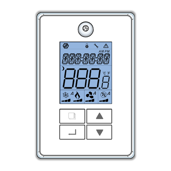
The signal icon indicates network connection status Display Icons Visible and fixed static = Online to both the BACnet MSTP network and the Strato Automation server Blinking = Online to the BACnet MSTP network only Local LCD The lock icon indicates that setpoints have been locked from the network and cannot be modified by the thermostat keys... -
Page 14: Display Messages On Local Lcd Display
Display AI-1 and AI-2 as external inputs Display Messages Messages MSV100 Message Sequence of each input selection Local LCD None (None): No function will be associated with the input (NSB Night Setback): NSB timer clock input. The scheduling will now be set as per the binary input. It provides low-cost setback operation via a dry contact. Rem NSB Ovr Contact opened = Unoccupied Contact closed = Occupied... -
Page 15: Cooling And Heating Stages Application Note
Cooling and heating stages Application Note (Binary outputs staging): There is a fixed 3 min delay before the first stage of heating or cooling will start. There is a 1 min delay for each stage afterward. See Binary Output demand curves on each sequence in this guide. (Heating/Cooling Change Over): There is a fixed 3 min delay before the first stage of heating or cooling will start when changing over from heating or cooling Change Over for both Binary and Analog outputs. -
Page 16: Using The Menus
Using the menus Network Configuration Settings Set the BW437-RTU’ s configuration in the “CONFIG MODE” directly on the BW437-RTU’ s screen using the keypad. To be able to do so, press simultaneously buttons for 3 seconds. Press these PIN keys in sequence on the BW437-RTU’ s keypad... - Page 17 Using the menus Setup menu (quick setup) Access the “SETUP MENU” directly on the BW437RTU’ s screen using the keypad. To be able to do so, press simultaneously buttons for 3 seconds. Press these PIN keys in sequence on the BW437RTU’ s keypad SETUP will appear on the screen for 1 second The first configurable object to be displayed in the SETUP menu is the PIPENUM This is the one used for this next example...
- Page 18 Using the menus Setup menus (quick setup) Object Setup menu Description Options Function Instance MSV127 See Table Next page Preset Select application MSV64 CFGunit Units configuration Metric Sets the system for using metric units (Degree C) Imper Sets the system for using imperial units (Degree F) MSV1 CFGSens Remote thermistor type...
- Page 19 Using the menus Setup menus (quick setup) Table Object Instance MSV 127 Dehumid Humidifier Humidifier Application Htg Stg 1 Htg Stg 2 Mod Htg Clg Stg 1 Clg Stg 2 Clg Stg 3 Clg Stg 4 Rev Valve Econ Mod CO2 RT 2STG RT ECON HP 2STG...
- Page 20 Installation I/O Wiring & Sequence MSV127 – RT 2STG Rooftop unit (2 cooling / 2 heating) 24VAC RT 2STG: Sets for a 1 on/off fan, 2 on/off heat & 2 on/off cooling stages RTU unit Notes: - BO6 is an occupancy output that follows the main occupancy - BO7 is an on/off power exhaust that follows the main occupancy when the main fan BO1 is on AO1/BO7...
- Page 21 Installation I/O Wiring & Sequence MSV127 – RT 2STG Sequence of operation Occupied Mode: Setpoints will revert to those defined by occupied cooling and 2 stages heating setpoints • Fan needs to be on Occupied Override Mode: The system will revert to occupied mode for the •...
- Page 22 Installation I/O Wiring & Sequence MSV127 – RT ECON Rooftop unit (2 cooling / 2 heating) 24VAC RT 2STG: Sets for a 1 on/off fan, 2 on/off heat & 2 on/off cooling stages RTU unit Notes: - BO6 is an occupancy output that follows the main occupancy - BO7 is an on/off power exhaust that follows the main occupancy AO1/BO7 when the main fan BO1 is on...
- Page 23 Installation I/O Wiring & Sequence MSV127 – RT ECON Free cooling 100% Sequence of operation • Economizer OAT Changeover is set at: AV29 OAT, Property Occupied Mode: Setpoints will revert to those defined by occupied cooling and heating setpoints ID 516, Index 2 •...
-
Page 24: Economizer
Installation I/O Wiring & Sequence MSV127 – RT ECON Economizer The controller can be configured with the economizer option to take advantage of free cooling. The two Control Types of that can be configured are Off-Auto or Modulating control. Dry Bulb The economizer is enabled to utilize free cooling when there is a call for cooling and the outside air temperature is less than the OAT Econo Authorization setpoint. -
Page 25: Heat
Installation I/O Wiring & Sequence MSV127 – HP 2STG Heatpump (2 compressors / 1 On/Off heating) 24VAC HP 2STG: Sets for a 1 on/off fan, 2 on/off heatpump, 1 on/off reheat, 1 reversing valve stage with 0-10 VDC economizer HEATPUMP unit Notes: - BO6 is an occupancy output that follows the main occupancy - BO7 is an on/off power exhaust that follows the main occupancy... - Page 26 Installation I/O Wiring & Sequence MSV127 – HP 2STG Sequence of operation Occupied Mode: Setpoints will revert to those defined by occupied cooling and 2 heatpump + 1 Aux heating stages 2 Heatpump stages cooling mode heating setpoints BO.5 ON •...
- Page 27 Installation I/O Wiring & Sequence MSV127 – RT IAQ Rooftop unit IAQ (2 cooling / 2 heating) RT IAQ: Sets for a 1 on/off fan, 2 on/off heat, 2 on/off 24VAC cooling stages with 0-10 VDC economizer RTU unit. model needed Notes: - BO7 is an on/off power exhaust that follows the main occupancy when the main fan BO1 is on...
- Page 28 Installation I/O Wiring & Sequence 2 stages MSV127 – RT IAQ • Fan needs to be on • Call For Cooling or Sequence of operation Heating at least 180 2 stage ON seconds Occupied Mode: Setpoints will revert to those defined by occupied cooling and heating setpoints •...
- Page 29 Installation I/O Wiring & Sequence MSV127 – RT MOD Rooftop unit Mod (2 cooling / 2 heating) 24VAC RT MOD: Sets for a 1 on/off fan, 1 on/off heat with [1] 0- 10 VDC heating, 2 on/off cooling stages. Notes: - BO6 is an occupancy output that follows the main occupancy - BO7 is an on/off power exhaust that follows the main occupancy when the main fan BO1 is on...
- Page 30 Installation I/O Wiring & Sequence MSV127 – RT MOD 2 stages Sequence of operation • Fan needs to be on • Call For Cooling at least 180 seconds Occupied Mode: Setpoints will revert to those defined by occupied 2 stage ON •...
- Page 31 Installation I/O Wiring & Sequence MSV127 – HP DEH Heatpump HP DEH: Sets for a 1 on/off fan, 2 on/off heatpump, 1 (2 compressors / 1 dehum) on/off dehumidification. 24VAC Notes: - BO6 is an occupancy output that follows the main occupancy - BO5 is an on/off dehumidification output that follows dehumidification demand Dehum...
- Page 32 Installation I/O Wiring & Sequence MSV127 – HP DEH Sequence of operation 2 Heatpump stages Heating and cooling mode Occupied Mode: Setpoints will revert to those defined by occupied cooling and heating setpoints Occupied Override Mode: The system will revert to occupied mode for the duration determined by the “OvrTime_Set AV27”...
- Page 33 Installation I/O Wiring & Sequence MSV127 – HUM-DEH (RTU) Rooftop unit HUM-DEH HUM-DEH: Sets for a 1 on/off fan, 2 on/off heat, 2 on/off (2 Cooling / 2 Heating) cooling, 1 on/off dehumidification stages with 0-10 VDC or On/Off humidifier. 24VAC Notes: BO6 is an on/off dehumidification output that follows...
- Page 34 Installation 2 stages I/O Wiring & Sequence • Fan needs to be on MSV127 – HUM-DEH (RTU) • Call For Cooling or Heating at 2 stage ON least 180 seconds Sequence of operation 1 stage ON • There is a 60 seconds between each stages Occupied Mode: Setpoints will revert to those defined by occupied cooling and heating setpoints...
- Page 35 Installation I/O Wiring & Sequence MSV127 – RT 3STG Rooftop unit (3 cooling / 2 heating) RT 3STG: Sets for a 1 on/off fan, 2 on/off heat & 3 on/off cooling stages RTU unit 24VAC Notes: - BO7 is an occupancy output that follows the main occupancy - AI’s can be configured for various options as per MSV2, 27, 28, 66 &...
- Page 36 Installation I/O Wiring & Sequence MSV127 – RT 3STG 2 heat stages Sequence of operation 2 stage ON Occupied Mode: Setpoints will revert to those defined by occupied cooling and heating setpoints 1 stage ON Occupied Override Mode: The system will revert to occupied mode for the duration determined by the “OvrTime_Set AV27”...
- Page 37 Installation I/O Wiring & Sequence MSV127 – RT 4STG Rooftop unit (4 cooling / 2 heating) RT 4STG: Sets for a 1 on/off fan, 2 on/off heat & 4 on/off 24VAC cooling stages RTU unit Notes: - AO4 is an occupancy output that follows the main occupancy where 0% = unoccupied and 100% = occupied - AI’s can be configured for various options as per MSV2, 27, 28, 66 &...
- Page 38 Installation I/O Wiring & Sequence MSV127 – RT 4STG 2 heat stages Sequence of operation Occupied Mode: Setpoints will revert to those defined by occupied cooling 2 stage ON and heating setpoints 1 stage ON Occupied Override Mode: The system will revert to occupied mode for the duration determined by the “OvrTime_Set AV27”...
- Page 39 Installation I/O Wiring & Sequence MSV127 – HP 3STG HP 3STG: Sets for a 1 on/off fan, 3 on/off heatpump, 1 on/off reheat. Notes: - BO7 is an occupancy output that follows the main occupancy - AI’s can be configured for various options as per MSV2, 27, 28, 66 &...
- Page 40 Installation I/O Wiring & Sequence MSV127 – HP 3STG Sequence of operation Occupied Mode: Setpoints will revert to those defined by occupied cooling and heating setpoints Occupied Override Mode: The system will revert to occupied mode for the duration determined by the “OvrTime_Set AV27” parameter 3 Heatpump Heating 3 Heatpump Cooling On a call for cooling / System mode is Cooling or Auto: Reversing valve will be set in...
- Page 41 Installation I/O Wiring & Sequence MSV127 – HP 4STG HP 4STG: Sets for a 1 on/off fan, 4 on/off heatpump, 1 on/off reheat. Notes: - BO7 is an occupancy output that follows the main occupancy - AI’s can be configured for various options as per MSV2, 27, 28, 66 &...
- Page 42 Installation I/O Wiring & Sequence MSV127 – HP 4STG Sequence of operation Occupied Mode: Setpoints will revert to those defined by occupied cooling and heating setpoints Occupied Override Mode: The system will revert to occupied mode for the duration 4 Heatpump Cooling determined by the “OvrTime_Set AV27”...
-
Page 43: Service Menu
Using the menus Service menus / Allows Keypad Access to all Objects Access the “Service menus” directly on the BW437-RTU’ s screen using the keypad. To be able to do so, press simultaneously buttons for 3 seconds. Press these PIN keys in sequence on the BW437RTU’ s keypad “SERVICE MODE”... - Page 44 Using the menus Test IO mode menu / Allows Local Testing of I/O’ s Access the “Test IO mode” directly on the BW437’ s screen using the keypad. To be able to do so, press simultaneously buttons for 3 seconds. Press these PIN keys in sequence on the BW437RTU’...
-
Page 45: Physical Inputs And Outputs
Physical Inputs and Outputs (AI’ s , AO’ s , BI’ s & AO’ s ) Object Description Default Tags Minimum Maximum Inactive_Text Active_Text Instance Object name value range value range value BO_1 Based on MSV127 config Status BO_2 Based on MSV127 config Status BO_3 Based on MSV127 config... -
Page 46: Analog Values
Analog Values Object Description Tags Default value Minimum Maximum Instance Object name range value range value RoomTSP Room Temperature setpoint User 72°F (22°C) 54°F (12°C) 90°F (32°C) HTG_Dem Heating demand Status 100% CLG_Dem Cooling demand Status 100% Eff_T Effective temperature used for control Status -40°F (-40°C) 122°F (50°C) - Page 47 Analog Values Object Description Tags Default value Minimum Maximum Instance Object name range value range value AV50 RT_Cal Room temperature calib 0.0°F (0.0°C) -3.0°F (-3.0°C) 3.0°F (3.0°C) AV51 Eff_RH Effective humidity used for control Status 100% AV52 HUM_SP Set humidity setpoint 100% AV53 Supply humidity reading...
-
Page 48: Binary Values
Binary Values Object Description Tags Default Inactive_Text Active_Text Instance Object name value OVRSTAT Occupancy override status Status Normal Normal Overrid Mot_Det Motion detection Status Moving None Moving AutogenDesc Autogenerate I/O descriptions Occ_Sch System occupancy schedule Status Freeze_Status Freeze condition status Status Normal Active... -
Page 49: Multi-State Values
Multi-State Values Object Description Tags Default value State texts Instance Object name MSV1 CFGSens Remote thermistor 10K Type 3 Type 3 Type 2 MSV2 AI_RS Select room temperature input Intern Intern AI-1 AI_2 AI-3 AI-4 MSV3 MODE System mode User Auto Cool Heat... - Page 50 Multi-State Values Object Description Tags Default value State texts Instance Object name MSV7 CFG_Y1 Set cooling output 1 operation None None Off-On 0-10V D(direct) 0-10V R(reversed) 2-10V D(direct) 2-10V R(reversed) Pulsed D(direct) Pulsed R(reversed) MSV8 CFG_Y2 Set cooling output 2 operation None ‘’Same as above’’...
- Page 51 Multi-State Values Object Description Tags Default value State texts Instance Object name MSV16 CFG_W1 Set heating output 1 operation None None Off-On 0-10V D(direct) 0-10V R(reversed) 2-10V D(direct) 2-10V R(reversed) Pulsed D(direct) Pulsed R(reversed) O (O/B) B (O/B) MSV17 CFG_W2 Set heating output 2 operation None ‘’Same as above’’...
- Page 52 Multi-State Values Object Description Tags Default value State texts Instance Object name MSV23 CFG_FAN Select fan output BO1_AO1 BO1_AO2 MSV27 AI_OAT Select outside air temp. input None None AI-1 AI-2 AI-3 AI-4 External MSV28 AI_SAT Select supply air temp. input None ‘’Same as above’’...
- Page 53 Multi-State Values Object Description Tags Default value State texts Instance Object name MSV32 CFG_EXH Select power exhaust output None None BO-6 BO-7 AO-4 BO-6 & AO-4 BO-7 & AO-4 MSV44 BI_PIR Select PIR Motion sensor input Intern NO, AI1 (BI) NC, AI1 (BI) NO, AI2 (BI) NC, AI2 (BI)
- Page 54 Multi-State Values Object Description Tags Default value State texts Instance Object name MSV45 BI_SCH_Input Select schedule input None None (Off) None (On) Scheduler AI-1 AI-2 AI-3 AI-4 External Please note that objects tagged as: • Cfg: represent configuration properties of the device that are typically only set once during commissioning and start-up •...
- Page 55 Multi-State Values Object Description Tags Default value State texts Instance Object name MSV48 BO_HUM Select humidifier BO output None None BO-2 BO-3 BO-4 BO-5 BO-6 BO-7 BO-5+BO-6 (2stages) BO-6+BO-7 (2stages) MSV49 AO_HUM Select humidifier AO output None None AO-1 AO-2 AO-3 AO-4 MSV52...
- Page 56 Multi-State Values Object Description Tags Default value State texts Instance Object name MSV54 AI_SRH Select supply humidity input None None AI-1 AI-2 AI-3 AI-4 External MSV55 AIC_SRH Set supply humidity input signal 0-10V 0-10V 2-10V MSV57 OAH_Loc Outside humidity physical input loc. None None AI-1...
- Page 57 Multi-State Values Object Description Tags Default value State texts Instance Object name MSV62 CFGSetp Room setpoint displayed Heat SP Heat SP Center Cool SP MSV64 CFGUnit Unit configuration Imper Metric Imper(ial) MSV65 BO_OCC Select occupied output None None Please note that objects tagged as: •...
- Page 58 Multi-State Values Object Description Tags Default value State texts Instance Object name MSV66 AI1_CFG Select predefined AI1 logic None None FILTER SERVICE FANLOCK MSV67 AI2_CFG Select predefined AI2 logic None None FILTER SERVICE FANLOCK MSV68 BO_DEHU Select dehumidification output None None BO-2 BO-3...
- Page 59 Multi-State Values Object Description Tags Default value State texts Instance Object name MSV70 CFG Heating/cooling proportional band 5F 2.2C 3F 1.2C 4F 1.7C 5F 2.2C 6F 2.8C 7F 3.3C 8F 3.5C 9F 5.0C 10F 5.6C MSV75 KeyLock SCFG Keypad lock level None None Mode...
- Page 60 Multi-State Values Object Description Tags Default value State texts Instance Object name MSV100 HELP_mess Help message Status Normal Normal Fanlock Supply Frozen Service Filter Rem NSB Ovr MSV127 Preset Select application RT 2STG RT 2STG RT ECON HP 2STG RT IAQ RT MOD HP DEH HUM-DEH...
-
Page 61: Rs485 Network Guidelines
RS485 Network Guidelines... - Page 62 RS485 Network Guidelines...
- Page 63 RS485 Network Guidelines...
- Page 64 RS485 Network Guidelines...
- Page 65 RS485 Network Guidelines...
-
Page 66: Specifications
Technical Specifications WARNING: Internally, this device utilizes a half-wave rectifier and therefore can only share the same AC power source with other half-wave rectified devices. www.stratoautomation.com...
Need help?
Do you have a question about the BW437-RTU and is the answer not in the manual?
Questions and answers