
Summary of Contents for BACH-SIMPSON Event Recorder 54300 Series
- Page 1 BACH-SIMPSON ® INSTRUMENTATION and CONTROL EQUIPMENT Event Recorder System 54300 Series Operation & Maintenance Manual...
- Page 2 Revision Date Description of Changes (yy.mm.dd) Initial Release 06.01.03 Modified section 1.7, 3.2, 3.4, 3.6, 4.2, 5.3 Added section 2.5. Bach-Simpson Corporation 1255 Brydges Street London, Ontario, Canada www.bach-simpson.com BACH-SIMPSON ® CM54300 Rev A ERS Manual INSTRUMENTATION and CONTROL EQUIPMENT...
-
Page 3: Table Of Contents
4.3 Portable Test Equipment (PTE) Diagnostics ......23 4.4 WinDNLD Functionality ............26 4.5 Download Options ..............30 Corrective Maintenance.............. 32 5.1 Introduction................32 5.2 Adjustments and Alignment ..........32 5.3 Removal & Repair ..............32 BACH-SIMPSON ® CM54300 Rev A ERS Manual INSTRUMENTATION and CONTROL EQUIPMENT... - Page 4 Event Recorder System Maintenance & Operation Manual Series 54000 Acronyms BSC: Bach-Simpson Corporation BTE: Bench Test Equipment CCW: Counter-Clockwise ERS: Event Recorder System ERU: Event Recorder Unit HMM: Hardened Memory Module Processor Module PWM: Pulse Width Modulator TMS: Train Monitoring System...
- Page 5 Table 4-2. WinDNLD Main Menu Bar...........24 Table 4-3. WinDNLD Connection Options ........25 Table 4-4. Troubleshooting Communications ......25 Table 4-5. Summary Screen Items ..........26 Table 4-6. Real -Time Hot Key Command Summary....30 BACH-SIMPSON ® CM54300 Rev A ERS Manual INSTRUMENTATION and CONTROL EQUIPMENT...
-
Page 6: Introduction
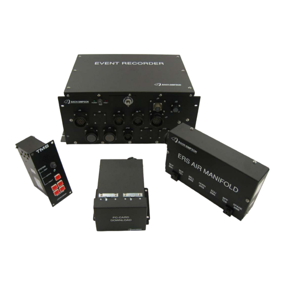
Series 54000 1 Introduction This document contains information about the Bach-Simpson 54000 series Event Recorder System (ERS). A typical system consists of the event recorder, a Train Monitoring System (TMS), PC-Card Download Unit, an air manifold and associated cables and connectors. -
Page 7: Figure 1-2. Typical Event Recorder Exterior
Event Recorder System Maintenance & Operation Manual Series 54000 Figure 1-2. Typical Event Recorder Exterior BACH-SIMPSON ® CM54300 Rev A ERS Manual INSTRUMENTATION and CONTROL EQUIPMENT... -
Page 8: Equipment Description - External
The event recorder consists of the following major components: A Hardened Memory Module (HMM) A Power Supply Module (PS) A Processor Module (PM) A Frequency/LonWorks Communications ID Module (FLID) Digital Boards Analog Input Board(s). Output Board BACH-SIMPSON ® CM54300 Rev A ERS Manual INSTRUMENTATION and CONTROL EQUIPMENT... -
Page 9: Figure 1-3. Event Recorder - Typical Interior
POWER SUPPLY DIGITAL BOARD BOARD 72-VOLT ISOLATED ANALOG BOARD DIGITAL BOARD FREQUENCY/ LONWORKS/ ID BOARD CRASH HARDENED MEMORY MODULE PROCESSOR MODULE BOARD MET004 Figure 1-3. Event Recorder – Typical Interior BACH-SIMPSON ® CM54300 Rev A ERS Manual INSTRUMENTATION and CONTROL EQUIPMENT... -
Page 10: Pc-Card Download Unit
It is mounted in the train cab. It contains a slot into which a PC data card may be inserted, as well as an LED status indicator and a download port. These are located under the flip-up cover panel. BACH-SIMPSON ® CM54300 Rev A ERS Manual... -
Page 11: Train Monitoring System
It is a small metal box with an audible alarm, a test button and various alarm and fault LEDs. It is mounted in the train cab and connected to, and controlled by the ERS. BACH-SIMPSON ® CM54300 Rev A ERS Manual... -
Page 12: Air Manifold
The air manifold is a small metal box that receives signals from pressure transducers and pressure switches throughout the train. It is connected to the event recorder by a single cable. Figure 1-6. Air Manifold BACH-SIMPSON ® CM54300 Rev A ERS Manual... -
Page 13: Reference Data
This table lists the parameters that must be recorded. These signals are obtained by using a combination of discrete transducers, existing sensors and onboard equipment. Refer to CD drawing for specific signal descriptions and system connections. BACH-SIMPSON ® CM54300 Rev A ERS Manual... - Page 14 (CBTC) control signals Advanced Civil Speed Enforcement System Network or Digital (ACSES) Status Doors Closed summary trainline Digital Doors Locked summary trainline Digital Table 1 - IEEE 1482.1 Signals to Monitor BACH-SIMPSON ® CM54300 Rev A ERS Manual INSTRUMENTATION and CONTROL EQUIPMENT...
-
Page 15: Functional Description
(downloading) operations. The HMM memory is logically arranged as a circular buffer and the data is stored using flash technology that does not require any power to maintain its status. BACH-SIMPSON ® CM54300 Rev A ERS Manual... - Page 16 The input signals are scaled to ranges that can be measured and recorded by the Processor Module. Analog input module The analog inputs are directed to the pressure/spare analog board. BACH-SIMPSON ® CM54300 Rev A ERS Manual INSTRUMENTATION and CONTROL EQUIPMENT...
-
Page 17: Event Recorder Block Diagram
The ERS controls an internal timer that starts counting down after any one of a number of different operator signals, actions or operating conditions are met. The faster that the train is traveling, the less time the operator has to perform one of these actions to reset the timer. BACH-SIMPSON ® CM54300 Rev A ERS Manual... -
Page 18: Figure 2-2. Event Recorder Override Switch - If So Equipped
1 second. TMS Reset Sources A change in any of the predetermined inputs will reset the Train Monitoring System timer (when it is enabled): BACH-SIMPSON ® CM54300 Rev A ERS Manual INSTRUMENTATION and CONTROL EQUIPMENT... -
Page 19: Table 2-1 Typical Tms Timing Chart
Penalty Initiation TMS Panel alarm lights on continuous, audible 13 seconds to start alarm silent. Penalty output relay contacts open of Penalty Reclaim causing a brake application. BACH-SIMPSON ® CM54300 Rev A ERS Manual INSTRUMENTATION and CONTROL EQUIPMENT... -
Page 20: Horn Sequencer Function Description
3.0 Seconds "OFF" 2.0 Seconds Long Blast "ON" 3.0 Seconds "OFF" 2.0 Seconds Short Blast "ON" 1.0 Seconds "OFF" 2.0 Seconds Long Blast "ON" 3.0 Seconds "OFF" 2.0 Seconds BACH-SIMPSON ® CM54300 Rev A ERS Manual INSTRUMENTATION and CONTROL EQUIPMENT... -
Page 21: Scheduled Maintenance
Table 3-1. Scheduled Maintenance REQUENCY QUIPMENT ERFORMS Quarterly Event Recorder 1. 92 Day Inspection. Transit Authority. 10 Year Event Recorder 1. Replace HMM and clock battery. Bach-Simpson Corp. 2. Re-flash EPROM. BACH-SIMPSON ® CM54300 Rev A ERS Manual INSTRUMENTATION and CONTROL EQUIPMENT... -
Page 22: Preventive Maintenance Procedures
LED on, pulses off for 0.1 second every 3 seconds. Processor Failure LED on steady (hardware forced condition of PM). Vcc Power Supply LED off steady (no power for LED). Failure BACH-SIMPSON ® CM54300 Rev A ERS Manual INSTRUMENTATION and CONTROL EQUIPMENT... -
Page 23: Operational Verification
If such a signal exists, it should be exercised manually and observed on the PIU Real Time Display to confirm that the signal is operational. A typical activity report is shown below. BACH-SIMPSON ® CM54300 Rev A ERS Manual INSTRUMENTATION and CONTROL EQUIPMENT... -
Page 24: Table 3-3. Sample Activity Inspection Report
Event Recorder System Maintenance & Operation Manual Series 54000 Table 3-3. Sample Activity Inspection Report BACH-SIMPSON ® CM54300 Rev A ERS Manual INSTRUMENTATION and CONTROL EQUIPMENT... -
Page 25: Figure 3-1 Download Summary Report
Activity Inspection Report. The download summary confirms the recording duration (> 48 hours) while Activity Inspection Report confirms the recording activity. Figure 3-1 Download Summary Report BACH-SIMPSON ® CM54300 Rev A ERS Manual INSTRUMENTATION and CONTROL EQUIPMENT... -
Page 26: Troubleshooting
Replace ERS with spare Return defective ERS to LONworks/input board unit. manufacture. failure. Network interface fault. Fault on FLID board. Replace ERS with spare Return defective ERS to unit. manufacture. BACH-SIMPSON ® CM54300 Rev A ERS Manual INSTRUMENTATION and CONTROL EQUIPMENT... - Page 27 Return defective ERS unit. to manufacture. Steady red fault LED on Any of the above faults. Replace ERS with spare Return defective ERS event recorder front panel. unit. to manufacture. BACH-SIMPSON ® CM54300 Rev A ERS Manual INSTRUMENTATION and CONTROL EQUIPMENT...
-
Page 28: Portable Test Equipment (Pte) Diagnostics
(Summary View, Real-Time View, Download, etc.). Selecting a menu title will make the program display sub menus. The menu bar appears on many modules in the WinDnld program. BACH-SIMPSON ® CM54300 Rev A ERS Manual INSTRUMENTATION and CONTROL EQUIPMENT... -
Page 29: Figure 4-2. Sub-Menu Example
Alternatively, the menu items can be selected using the mouse or pressing the keyboard character corresponding to the underlined character in the menu item. BACH-SIMPSON ® CM54300 Rev A ERS Manual... -
Page 30: Table 4-3. Windnld Connection Options
Using the wrong cable could cause damage to the event recorder or the laptop. Many retries during download Lower download baud rate. Disable SmartDrive disk caching Disable energy saving mode. BACH-SIMPSON ® CM54300 Rev A ERS Manual INSTRUMENTATION and CONTROL EQUIPMENT... -
Page 31: Windnld Functionality
Indicate if the event recorder has a fault (Fault) or not (None). Not available for TMACS. Previous Dnld: The date and time of the previous download. Not available for TMACS. BACH-SIMPSON ® CM54300 Rev A ERS Manual INSTRUMENTATION and CONTROL EQUIPMENT... -
Page 32: Figure 4-3. Summary Screen
View the Event Recorder in Real-Time Mode. The Real-Time display is a continuously updated representation of the channel values of the event recorder. The event recorder must be BACH-SIMPSON ® CM54300 Rev A ERS Manual... -
Page 33: Figure 4-5. Customized Real-Time Display
The default layout is the custom layout. Figure 4-5. Customized Real-Time Display is a snapshot of customized Real-Time display screen. The Layout button toggles the display layout between custom and standard layouts. BACH-SIMPSON ® CM54300 Rev A ERS Manual INSTRUMENTATION and CONTROL EQUIPMENT... -
Page 34: Figure 4-6. Diagnostics Screen
Use the Pressing the Close button will stop the Real-Time display and return to the main menu. Figure 4-6. Diagnostics Screen The Diagnostics Screen has a fixed layout and physical connection channel labels. This screen is used for troubleshooting and technical support. BACH-SIMPSON ® CM54300 Rev A ERS Manual INSTRUMENTATION and CONTROL EQUIPMENT... -
Page 35: Download Options
Partial Downloads set a size limit on downloads. Set this limit by selecting one of the sizes in the Limit Size menu. The current sizes available are 2048, 1024, 768, 512 and 256 Kbytes. BACH-SIMPSON ® CM54300 Rev A ERS Manual... -
Page 36: Figure 4-7. Download Screen
Figure 4-8. Selecting a Download Baud Rate The selected baud rate will become the default rate for following downloads. The default baud rate is restored from the configuration file. BACH-SIMPSON ® CM54300 Rev A ERS Manual INSTRUMENTATION and CONTROL EQUIPMENT... -
Page 37: Corrective Maintenance
3. Remove four hold down bolts securing event recorder to bracket. 4. Remove event recorder from train. 5. Observe these steps in reverse order to install event recorder into train. BACH-SIMPSON ® CM54300 Rev A ERS Manual INSTRUMENTATION and CONTROL EQUIPMENT...
Need help?
Do you have a question about the Event Recorder 54300 Series and is the answer not in the manual?
Questions and answers