Table of Contents

Summary of Contents for SMART CORE SC-16
- Page 1 OPERATION MANUAL OPTICAL FIBRE FUSION SPLICER SMARTCORE SC-16 Please read this Operation Manual carefully before operating the equipment. Comply with all safety procedures and warnings in this manual. Keep this manual properly in a safe place. Issued on 2020-5-9...
-
Page 2: Warnings And Cautions
WARNINGS AND CAUTIONS The Optical Fibre Fusion Splicer is designed for the optical quartz glass fibre used in the communications, except which it cannot be used to splice any other substances and for other applications. Considering the user’s personal safety, here we provide the user with a lot of safety cautions,because it is possible to result in electric shock, fire and personal injury if the user improperly uses the Optical Fibre Fusion Splicer. -
Page 3: Product Introduction
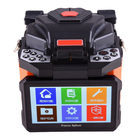
PRODUCT INTRODUCTION... - Page 4 MAIN POINTS OF FUSION SPLICING PROCEDURES 1. How to Get Small Splicing Loss 1-1.Necessary Regular Cleaning Jobs ▪ Clean V-Shaped Groove ▪ Clean Reflecting Mirror ▪ Clean Optical Fibre Pressure Head Clean Objective Lense. In case of cleaning Objective Lens , it is ▪...
- Page 5 Please put the end of the optical fibre at the place between the edge of the V- shaped groove and the center of electrode. Please put the optical fibre rightly on the bottom of the V-shaped groove. Make sure the correct cut length. If the cut length is too short, the optical fibre’s coating edge may possibly encounter the V-shaped groove, so that two optical fibers can not be, in the discharge process, fully close to each other, resulting in undesirable loss of fusion splicing.
- Page 6 2. Power Supply Please only use the AC Adaptor provided by the manufacturer. Please only use the Storage Battery and Battery Charger provided by the manufacturer. 2-1. Avoidance of Damage to AC Adapter The AC generators may possibly produce abnormal output of AC high voltage or irregular frequency.
-
Page 7: Basic Operations
BASIC OPERATIONS POWER CONNECTION OPTICAL FIBRE FUSION SPLICER provide two power-supply modes: ① Storage Battery; Adapter. Please make sure that OPTICAL FIBRE FUSION ② SPLICER shall be turned off .in case of operating it. 1-1.Insertion of the Storage Battery. Insert the storage battery into the battery slot until it is properly in place. 1-2. -
Page 8: Splicing Operation
TURNING ON POWER OF OPTICAL FIBRE FUSION SPLICER Press power button to switch ON/OFF device. 3. LAYING OPTICAL FIBRE To open the wind-protector cover and the optical fibre clamp cover; To get the ready optical fibre to be placed in the V-shaped groove, and make the end of optical fiber be placed at the position between the edge of the V-shaped groove and the electrode tip;... - Page 9 4-3.Pause Functions: Open/Close Open: After the completion of the core-to-core, press the key to perform the fusion splicing. Close: After the completion of the core-to-core, automatically perform the fusion splicing. 5. TAKING OUT OPTICAL FIBRE AND HEAT IT UP Open the heater lid; Open the windproof cover;...
- Page 10 MAINTENANCE OF FUSION SPLICING QUALITY CLEANING AND CHECKING BEFORE FUSION SPLICING The following describes the maintenance checks for the key cleaning points and the important parts. 1-1.Cleaning the V-Shaped Groove If there are dusts or contaminations in the V-shaped groove, the optical Fiber Pressure Head can not suppress the Optical Fiber correctly, resulting in that the loss of fusion splicing is larger.
- Page 11 1-2. Cleaning Up the Optical Fiber Pressure Head If there are contaminations on the Optical Fiber Pressure Head, the optical Fiber Pressure Head can not suppress the Optical Fiber normally, resulting in degrading the quality of fusion splicing. ● To open the windproof cover. ●...
- Page 12 rubber pad with a cotton swab just having had a dip in alcohol (above 99% alcohol) 1-5. Discharge Tests Atmospheric environment, such as: temperature, humidity, air pressure, is constantly changing, so that the discharge temperature is also changing. Due to the electrode wear, it is unable to automatically correct the discharge strength caused by the bonding of the optical Fiber debris.
- Page 13 Using a cotton swab just having had a dip in alcohol (above 99% alcohol), ◦ to gently wipe the surface of the objective lens, starting the wipe from the middle of the lens to do a circular movement until the edge of the lens, and repeating several times until there are no contaminations or stains or stripes.
- Page 14 MENU 1. Menu: Common Function 1-1. “Arc Test”...
- Page 15 In order to ensure the stable fusion-splicing quality, the user should operate regularly. It is necessary to do arc test in case of using the Optical Fiber Fusion Splicer under the following conditions: ultra-high temperature, ultra-low temperature, very dry, very wet, electrodes degradation, fusion splicing of the heterogeneous optical fibers, cleanness, or after replacing the electrode.
- Page 16 1-2.“Language” Set the Language.( Default English) 1-3 “Para Check” This is an Automatic calibrated program, no need to modify manually...
- Page 17 1-4 “Arc Force” It is off when use normally. When turned on, it is still work when splicing even if the fiber is not proper to splice. Menu: “Parameter Set” 2-1.“Operation Mode” Press the key “ ” to enter the “Operation Mode” Menu; press the keys “ ▲ ”, “ ▼ ” to select one of the three operation modes, “FULL AUTO”...
- Page 18 FULL AUTO” Operation Mode After place the fibers, cover the windproof cover then do splicing automatically “AUTO” Operation Mode. After place the fibers, press “ ”, then the program for fusion splicing will automatically execute. In case of normal fusion-splicing operation, generally select the “AUTO”...
- Page 19 “ ” as a “Shift” key: It is able to move the cursor up or down, so as to select the operation commands. “ ” as an “Optical Fiber Forward” key: It is able to get the Optical Fiber to advance. ◀...
- Page 20 Procedure to change the detailed Parameters (DEFAULT is Factory settings, cannot be changed) Press the “▲”“▼” to select, press the to enter the menu need to be changed, press “▲”“▼”change 2-3. “Arc Parameter” The Arc Parameter menu is the splicing arc parameters using now. Press “▲”“▼”to select, press the to enter the menu needed to change, press the “▲”“▼”to change the Parameters, then press...
- Page 21 2-4. “Heat Mode” Press the to enter the “heat program” menu, press ▲”“▼” to choose the working mode “Auto” or “Manual ”. When the choosing finished, press to save the results. When changing finished, press to exit. “AUTO” mode Put the fiber protective sleeve in the heating box, close the heating box cover, it will heat automatically “Manual”...
- Page 22 2-5. “Heat Program” Press “▲”“▼”to select, press to enter the “heat Program” you want. Press the “▲”“▼” choose the Procedure Number you need to operate or change, press the to choose the Procedure you want(the red is the Procedure operating now).If need to change the Procedure Parameters, please repress to enter the Procedure to change the detailed Parameters (DEFAULT is Factory settings, cannot be changed).
- Page 23 2-6. “Heat parameter” The heat parameter is the current heating parameter. 3. Menu “System debug” 3-1. “Sensor Status”...
- Page 24 Check the status of each Sensor. 3-2. “Stabilize Electrodes”...
- Page 25 Sometimes when the outside environment changes, the Arc power will be unstable. That leads to a big splicing loss. Especially that when the fusion splicer from low altitude area to high altitude area, so it needs some time to stabilize Arc power. When this occasion, it needs to do several Arc tests to stabilize electrodes, which will speed up Arc power stabilization.
- Page 26 3-4. “Display Config-Manual” According to general splicing steps to strip, cut and place optical fiber. Press to enter the “Display Config-Manual”. The screen will show the follows: Place fiber and press Enter. Press after place the optical fiber. ◀ ▶ “...
- Page 27 3-6. Display Config – LED Press , select “Display Config -LED”, press to adjust lightness of X-axis, to adjust lightness of Y-axis.
- Page 28 3-7. Display Setting – Dust Check Check whether there is dust in the display system Press , enter Display Config – Dust Check Menu, check whether the screen show Dust Check Success.
- Page 29 3-8. Motor Forward Test , enter “Motor Forward Test” ,screen will show“ UP to test right motor, Press Down to test left motor”...
- Page 30 3-9. Motor Alignment Test Press , enter Motor Alignment Test, screen will show “UP to test X-axis motor, Down to test Y-axis motor”...
- Page 31 3-10. Moto Manually Test , enter Motor Manually Test ,press Prees to select the motor Left Moto Manual Trigger Press , select L Moto Manual Trigger, fix a cleaved fiber on the left fixture, make the fiber view in the screen, press and hold to move the fiber.
- Page 32 Press , select X Moto Manual Trigger, fix a cleaved fiber on the left fixture, make press and hold to move the fiber. the fiber view in the screen, Axis Moto Manual Trigger Press , select Y Moto Manual Trigger, fix a cleaved fiber on the right fixture, make press and hold to move the fiber.
- Page 33 Press , select Y Moto Auto Trigger, fix a cleaved fiber on the right fixture, make the fiber view in the screen, press to move the fiber automatically, press again to stop moving. 3-11. Menu of Fine Parameter Check Prees , enter Menu of Fine Parameter Check,according to the general method of fusion splicing, prepare 2 Single-Mode fiber which should be stripped, cleaved off,...
- Page 34 4、Menu: Machine Info You can check machine serial number, software version number, firmware version number and arc times from this menu. 4-1. Machine SN Machine serial number 4-2. Software Ver Machine software version number 4-3. Firmware Ver Machine firmware version number...
- Page 35 4-4. Arc Times Machine splicing arc times 4-5. Arc Records and check arc records by pressing “ ” ◀ “ , ▶”. Enter “Arc times” menu by pressing The machine can store 6000 times splicing arc records. 4-6. Update Software Update the machine software 4-7.
- Page 36 5、Other Config 5-1. “Pause” Press to enter “Pause” menu, press “▲”“▼”to choose the pause function “turn on or off” 。Press to ensure save the function after choosing. When do splicing, usually turn off the pause function. 5-2. Stretch Test to enter “Stretch Test” menu, press “▲”“▼”to choose “on”or “off” 。 Press Press to ensure save the function after choosing.
- Page 37 5-3. Monitor Flip Press to enter “Monitor Flip” menu, press “▲”“▼”to choose turn off or turn on of image rotaion. Press to ensure save the function after amending. Envisage image or rotate 180 to show the image on the screen.
- Page 38 5-4. Buzzer Volume Press to enter Buzzer Volume menu, press “▲”“▼” to choose turn off or turn on the button voice. Press to ensure save the function after choosing. 5-5. Time Set...
- Page 39 Press to enter “Time Set” menu, press“▲”“▼”to choose “year, month, date, hour, minute,”, press“ ” ◀, ▶ “ ” to amend the data. Press to ensure save the function after amending, then press to exist. 5-6. Function Setting Press to enter “Function Setting” menu, press “▲”“▼” to choose “saving power switch, Motor reset time”, press “▲”“▼”to amend the data.
- Page 40 5-7. Motor reset time Press to enter the "Motor Reset Time" function menu and press "▲" "▼" to modify the parameter. Press to save after modifying. And press to exit. 6. Menu: Quick Check 6-1. Arc parameter calibration Press to enter the “Arc parameter calibration”menu, according to the general fusion process to strip, cut and fix the fiber, and press to confirm.
- Page 42 6-2. Display parameter calibration Press to enter the “Display parameter calibration”menu, according to the general fusion process to strip, cut and fix the fiber, and press to confirm and test. Press to exit when the calibration is complete. According to general splicing steps to strip, cut and fix the fiber.
-
Page 43: Questions And Trouble Shooting
QUESTIONS AND TROUBLE SHOOTING TURNING ON POWER OF OPTICAL FIBRE FUSION SPLICER AND POWER SUPPLY Turn on the power switch, but the power supply does not respond. ● Reason: Power outlet is not plugged in. The contact of the power switch is bad. The storage battery is not properly inserted in. - Page 44 The display screen is bad. Solution: Check to see if the power supply fuse disconnects or not, and to see if there is the short-circuit or other failure occurs inside the optical fibre fusion splicer. Replace the power supply fuse on the main board. If there is the short-circuit or other failure inside the optical fibre fusion splicer, please contact your dealer to repair/maintain it or send it back to the factory for repair/maintenance.
- Page 45 Solution: please contact your dealer to repair/maintain it or send it back to the factory for repair/maintenance. FUSION SPLICING OPERATIONS After having placed the optical fibre, there appears a very dark image or a dim ● image on the half of the display screen. Reason: 1.
- Page 46 Solution: Produce the optical fiber again. Lay the optical fiber again. Shut the press board, and gently pull the optical fiber back by hand. If the optical fibre can be easily pulled to move, it indicates the press board did not pin the optical fiber. Check to see if the compaction bar of the optical fiber is able to bounce or not.
- Page 47 Reason: There is the dust on the precision V-shaped groove, so that the position of the optical fibre at one side is somewhat higher, the data of which is greater than the max. position value of the optical fibre at the other side moving up and down. There are the dust and dark spots on the objective lens’...
- Page 48 Solution: Produce the qualified optical fibre again. Clean in the same way, the objective lens’ surface, the lights, and the reflecting mirrors with a cotton swab just having had a dip in alcohol (above 99% alcohol), and remove the excess alcohol on the objective lens’...
- Page 49 Solution: Check to see if the selected program is correct or not, or to see if the set discharge strength in the program are proper or not. If it is still impossible to discharge normally, please contact your dealer to repair/maintain it or send it back to the factory for repair/maintenance.
- Page 50 Reason: The fusion-splicing current is too large, and the environmental humidity is too high. The advancing amount is somewhat small or is 0; the advancing speed value is somewhat large. The optical fibre’s press board did not pin the optical fibre. The quality of the optical fibre itself is poor, being disengaged from its cladding.
- Page 51 to solve these issues, please contact your dealer to repair/maintain it or send it back to the factory for repair/maintenance. ●The fusion splicing loss index has been somewhat large at all times. Reason: There is the dust on the optical fiber, and in the V-shaped groove of the Fusion Splicer.
-
Page 52: Heating Operation
●It is sparking on the electrodes or the electrode is sparking to the metals nearby it. Reasons: The electrode connecting cable is loose. The operating environment is humid. Solution: Check to see if the electrode connecting cable is loose or not. Change the operating environment to be the dry one, to see if there is the said phenomenon or there is not . - Page 53 The heating indicator light does not shine, but the normal heating can be done. ● Reason: The heater is faulty. The heating indicator light is bad. Solution: Please contact your dealer to repair/maintain it or send it back to the factory for repair/maintenance.
- Page 54 GUARANTEE AND CONTACT GUARANTEE 1-1.Warranty Period and Conditions If there occurs a failure in the optical fibre fusion splicer within one year starting from the date of goods delivery, we will provide a free repair/maintenance. However, we will not provide a free repair/maintenance within the Warranty Period, if there occur the following events: Failure or damage caused by natural disasters;...
- Page 55 The model and the serial number of the Optical Fibre Fusion Splicer. Problems about the Optical Fibre Fusion Splicer you have met: When did the Optical Fibre Fusion Splicer have the problem ? Which problem has happened? How about the present situation? and so on. 1-4.
Need help?
Do you have a question about the SC-16 and is the answer not in the manual?
Questions and answers