Advertisement
Table of Contents
Advertisement
Table of Contents

Related Manuals for Fnirsi DPS-150

Summary of Contents for Fnirsi DPS-150
- Page 1 DPS-150 便携式数控直流电源 PORTABLE CNC DC POWER SUPPLY...
- Page 3 目 录...
- Page 4 CATALOG...
- Page 5 用户须知 ●本手册详细介绍了产品的使用方法和注意事项, 请仔细阅读本手册按说明规范使用本产品, 以 便发挥产品的最佳性能。 ●不要在易燃、 易爆的环境中使用仪器。 ●仪器更换的废旧电池和报废的仪器不可与生活垃圾一同处理, 请按国家或者当地的相关法律规 定处理。 ●当仪器出现任何质量问题或者对使用仪器有疑问时, 可联系 “菲尼瑞斯-FNIRSI” 在线客服或厂 家, 我们将在第一时间为您解决。 一、 产品简介 FNIRSI-DPS150是我司推出的一款高性能可调直流稳压电源, 具备Type-C输入接口和多种供电方 式, 精准调节输出电压 (0-30V) 和电流 (0-5A) , 高效低耗且稳定输出, 配备多重安全保护功能, 包括 过压、 过流、 过载、 过热、 反接等, 灵活应用于多设备串联使用, 同时显示丰富且操作便捷, 人性化设 计尺寸小巧便于携带, 满足多种应用需求, 是为您提供高性能稳定的数控电源。...
- Page 6 二、 面板介绍 DC及Type-C供电接口 Micro数据传输接口 开关档位 2.8inch 运行/暂停按钮 屏幕 4.0mm香蕉头输出接口正负端 按键区域 调节滚轮...
-
Page 7: 过压保护
三、 参数介绍 型号 DPS-150 屏幕 2.8寸 (320*240) 电压 DC5.0V~32V 电压 0~30V 输出 电流 100mA~5A 电流 0~5A 输入 支持PD和QC快充协议, 充电宝 功率 0~150W 电压 10mV 电压 ≤0.1%±5mV 设定值精度 设定分辨率 电流 电流 ≤0.1%±3mA 负载调整率 0.49% 输入电压 ≤0.2%±5mV 回读值精度 满载效率 96.30% 输出电压 ≤0.1%±10mV ≤0.1%±5mA 尺寸... - Page 8 四、 操作说明 按键 按键方式 界面 功能 短按 运行 / 暂停 长按 锁定按键 短按 进入设置页面 计量开关关闭状态 清零时间 长按 计量开关打开状态 清零容量, 能量和时间 主界面 进入数据组页面 短按 波形显示界面 更换数据组 长按 波形显示界面 持续更换数据组...
- Page 9 按键 按键方式 界面 功能 主界面 切换数据组 短按 波形显示界面 减少时基 / 增加时基 设置页面出现高亮位 向左 / 向右 长按 页面出现高亮位时 持续向左循环 / 持续向右循环 主页面 页面出现高亮位 短按 设置页面 进入具体设置选项 长按 在主页面和波形显示页面中切换 左滑 在调节数字时, 减少数值 右滑 在调节数字时, 增加数值...
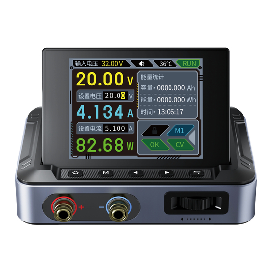
- Page 10 ①输入电压: 显示当前输入的供电电压, 单位V 32.00 V 输入电压 36℃ ②声音图标: 显示当前设备是否开启声音 ③温度显示: 显示当前设备内部的温度 能量统计 ④运行状态: 显示当前设备是否正在运行 0000.000 容量 2 0 . 0 设置电压 ⑤当前电压: 实时显示设备当前的电压, 0000.000 能量 单位V 13:06:17 时间 ⑥设置输出电压: 00.00~30.00V,分辨率 0.01V, 单位V 5 . 1 0 0 设置电流 ⑦当前电流:实时显示设备当前的电流, 单位A ⑧设置输出电流:...
- Page 11 ●控制面板锁定状态: 灰色表示未锁定, 锁定后 变为白色锁状态, 锁定后控制面板操作无效, 连 控制面板锁定状态 预设组 接上位机后自动锁定, 且不能通过按键解锁 工作状态 输出模式 ●输出模式: 包含两种, 恒压输出CV、 恒流输出 操作步骤: 参数调整: ①单击 , 进入参数调整状态, 设置电压处会出现高亮位, 再次单击 , 则会循环切换输出电压 设置和电流设置 ②通过 调节滚轮左滑右滑进行调整高亮位数值大小 预设数据组操作: ①在主页面短按 , 进入数据组预设界面 ②单击 , 出现高亮位, 再次单击 , 则会循环切换电压设置和电流设置 ③通过 调节滚轮左滑右滑进行调整高亮位数值大小 ④再次短按...
- Page 12 工作状态异常提示: ①状态异常红色提示, 包括过流保护、 过压保护、 过功率保护、 过热保护、 欠压保护、 反接保护, 并 关闭输出 菜单界面及操作: ①单击 进入菜单页面 ②通过按键 进行切换设置页面 ③单击 , 设置页面内出现高亮位, 通过 调节滚轮左滑右滑进行调整高亮位数值大小 ④设置完毕之后短按 进行保存退出 菜单项 可调范围 菜单项 可调范围 过压保护 0V~30.00V 语言设置 中文 / English 过流保护 0A~5.1A 风格切换 常规/工业风 过功率保护 0W~150.00W 亮度调节 可调 (档位越高背光越亮) 过温保护...
-
Page 13: Table Of Contents
过压保护 语言设置 中文 5.000 过流保护 风格切换 常规 工业风 150.00 过功率保护 亮度调节 过温保护 音量大小 型号: DPS-150 版本号: V1.0 设备地址: 001 05.00 欠压保护 计量开关 关 开 菜单界面 五、 上位机使用说明 5.1 基础功能界面 ①波形显示区域: 波形数据记录, 储存, 删除, 包括电压和电流, 当单独勾选查看其中一个波形时, 可以通过鼠标滚轮进行缩放查看 ②输出电压设置和电流设置: 改变当前预设组的输出电压和电流值 (仅改变不保存, 设备重启后仍... - Page 14 ⑥USB界面: 产品型号/固件版本/通讯速率/通讯端口/设备地址/联机状态 ⑦基本信息: 输入电压/输出电压/输出电流/输出功率/温度显示/状态显示 在此界面控制设备开启关闭状态 基础功能界面...
- Page 15 5.2 高级功能界面 ①序列输出: 以设定的序号范围和循环次数, 依次对设定的电压和电流参数进行定时输出。 点击开始执行序列输出 (其他界面锁定无效) , 已被执行的序号, 状态显示 OK, 未执行的序号显 示等待。 点击暂停, 保持当前序号输出; 点击继续则按照延时往下执行后面的 手动模式: 点击单步进行测试, 依次根据点击数测试, 停止将保持当前序号输出 ②电流扫描: 电压固定, 电流在设定范围内按照步进电流和延时进行扫描输出, 常用在恒流模式 下。 电压设定需要大于0V; 起始电流、 结束电流范围0.000A~5.000A (如果起始和结束值相同则 无效) ; 步进电流范围0.001A~5.000A; 延时时间1S~86400S,开始执行电流扫描输出 (其他界面 锁定无效) , 点击停止则停止扫描并关闭输出 ③电压扫描: 电流固定, 电压在设定范围内按照步进电压和延时进行扫描输出, 常用在恒压模式 下。...
- Page 16 高级功能界面...
- Page 17 5.3 上位机连接 ①将设备开启, 并使用Micro数据传输线将设备连接电脑 ②连接之后选择通讯端口, 可通过电脑管理中的设备管理器查看 ③点击联机, 在左边文本框内显示联机成功即可 ※注意: 在上位机连接过程中, 设备按键将被锁定, 无法操作 六、 固件升级 方法一: ①从官网获取最新的固件, 并解压下载到桌面 ②先按住 按键, 使用Micro数据传输线将设备连接电脑, 在进入固件升级模式, 此时电脑会弹 出U盘 ③将固件复制到U盘, 复制成功后, 设备自动升级固件 ④观察升级百分比, 升级完成后设备将会重启, 如升级失败请第一时间联系官方客服 方法二 (连接上位机软件) : ①在产品关于界面确认好设备地址与上位机软件显示的设备地址相同 ②使用Micro数据传输线将设备连接电脑, 确认好端口点击联机 ③出现联机成功提示, 点击上方的固件升级, 点击BOOT/重启 ④电脑会弹出U盘, 将固件复制到U盘, 复制成功后, 设备自动升级固件 ⑤观察升级百分比,...
- Page 18 固件升级界面...
- Page 19 七、 注意事项 ●产品工作在降压模式, 需要保证输入电压高于输出电压。 ●本产品供电范围DC5V~30V, 低于5.0V会欠压锁定禁止输出, 超过30V则可能会损坏设备。 建议 使用5V~30V电源供电。 ●当设备给感性负载和容性负载供电时, 建议先接好负载, 再开启设备输出。 ●当进行大功率输出时, 会有一定程度的发热, 这是正常现象, 建议在通风良好的环境使用 ●设备的两个供电口切记不可同时接电, 同时供电有概率会使电压低的输入源损坏 ●用于电池充电时, 强烈建议在输出端加上防倒倒灌模块(比如肖特基二极管)以保护设备不被损 坏 八、 生产信息 产品名称: DPS-150便携式数控直流电源 品牌/型号:FNIRSI/DPS-150 服务电话: 0755-28020752 生产商: 深圳市菲尼瑞斯科技有限公司 网址: www.fnirsi.cn 地址:广东省深圳市龙华区大浪街道伟华达工业园C栋西边8楼 执行标准:...
- Page 20 ●If you encounter any quality issues with the instrument or have any questions about its use, please contact "FNIRSI" online customer service or the manufacturer, and we will promptly assist you.
- Page 21 2. Panel Introduction DC and Type-C Power Switching Gears Micro Data Supply Interface Transmission Interface 2.8inch Screen Run/Pause Button Key Area Positive and Negative Terminals Adjustment Wheel of the 4.0mm Banana Plug Output Interface...
- Page 22 3. Parameter Introduction Model DPS-150 Screen 2.8Inch (320*240) Voltage DC5.0V~32V Voltage 0~30V Output Input Current 100mA~5A Current 0~5A Supports PD and QC fast Power 0~150W charging protocols, power bank Voltage 10mV Voltage ≤0.1%±5mV Set Resolution Set Value Precision Current Current ≤0.1%±3mA...
- Page 23 4.Operation Instructions Button Button Type Interface Function Short Press Run/Pause Long Press Lock Button Short Press Enter Settings Page Measurement Switch Off State Zero Time Long Press Measurement Switch On State Zero Capacity, Energy, and Time Main Interface Enter Data Group Page Short Press Waveform Display Interface Change Data Group...
- Page 24 Button Button Type Interface Function Switch Data Group Main Interface Decrease Time Base / Increase Time Base Short Press Waveform Display Interface Left / Right Highlight Appears on Setting Page Continuously Cycle Left / Long Press Highlight Appears on Page Continuously Cycle Right Highlight Appears on Page Main Interface...
- Page 25 Displays the current ①Input Voltage: input voltage, unit V. 32.00 V Input 36℃ ②Sound Icon: Indicates whether the Energy sound of the device is enabled. 0000.000 ③Temperature Display: Shows Vs e t 2 0 . 0 internal temperature of the device. 0000.000 ④Operating Status:...
- Page 26 ●Operating Status: Control Panel Lock Status Preset Group ①Normal OK Operating Status Output Modes ②Overvoltage Protection OVP ③Overcurrent Protection OCP ④Overpower Protection OPP ⑤Overheat Protection OTP ⑥Reverse Connection Protection REP ⑦Undervoltage Protection LVP ※When any status other than normal is detected, the device automatically shuts off the output and emits a beep alarm.
- Page 27 Operation Steps: Parameter Adjustment: ①Press , once to enter parameter adjustment mode. The highlight will appear at the voltage setting. Press again to cycle between output voltage and current settings. ②Use and the adjustment wheel to adjust the highlighted numerical value by scrolling left or right.
- Page 28 Abnormal Working State Prompt: ①Red color indication for abnormal status, including overcurrent protection, overvoltage protection, overpower protection, overheat protection, undervoltage protection, and reverse connection protection, followed by output shutdown. Menu Interface and Operations: ①Press once to enter the menu page. ②Use to switch between setting pages.
-
Page 29: 型号: Dps-150 版本号: V1.0
Sy s t e m A b o u t 30.00 Over voltage Language 中文 5.000 Over current Theme Regular 150.00 Over power Brightness Over tempe Volume 型号: DPS-150 版本号: V1.0 设备地址: 001 05.00 Under voltage Metering Open Close Menu Interfaces... - Page 30 5.Instructions for PC Software Use 5.1 Basic Function Interface ①Waveform Display Area: Records, stores, and deletes waveform data, including voltage and current. When viewing a single waveform, you can zoom in and out using the mouse scroll wheel. ②Output Voltage and Current Settings: Change the output voltage and current values of the current preset group (changes are temporary and not saved;...
- Page 31 Control Device On/Off Status On This Interface Basic Function Interface...
- Page 32 5.2 Advanced Function Interface ①Sequential Output: Within the specified range of sequence numbers and loop counts, sequentially output voltage and current parameters. Click "Start" to execute sequential output (other interfaces are locked and inactive). Numbers that have been executed show "OK", while numbers that haven't been executed show "Waiting". Click "Pause"...
- Page 33 Advanced Function Interface...
- Page 34 5.3 PC Software Connection ①Turn on the device and connect it to the computer using a Micro data transfer cable. ②After connection, select the communication port. You can view it through Device Manager in Computer Management. ③Click "Connect". Once "Connected" is displayed in the left text box, the connection is successful. ※NOTE:...
- Page 35 Method Two (Connecting to PC Software): ①On the device's About page, ensure that the device address matches the device address displayed in the PC software. ②Connect the device to the computer using a Micro data transfer cable. Confirm the port and click "Connect"...
- Page 36 Firmware Upgrade Interface...
- Page 37 7.Precautions ●The product operates in step-down mode, so ensure that the input voltage is higher than the output voltage. ●The power supply range for this product is DC 5V~30V. Output will be disabled if the input voltage is lower than 5.0V due to undervoltage lockout, and the device may be damaged if the input voltage exceeds 30V.
- Page 38 8.Production Information Any FNIRSI's users with any questions who comes to contact us will have our promise to get a satisfactory solution +an extra 6 months warranty to thanks for your support! By the way, we have created an interesting community, welcome to contact FNIRSI staff...
- Page 40 下载用户手册&应用软件 Download User manual&APP&Software...
Need help?
Do you have a question about the DPS-150 and is the answer not in the manual?
Questions and answers
Сгорела деталь маркировка ccp чем заменить