Table of Contents
Advertisement
Quick Links
Advertisement
Table of Contents

Summary of Contents for Fnirsi DWS-200
- Page 1 DWS-200 精密智能焊台使用说明书 Precision Intelligent Soldering Station Instruction Manual...
- Page 2 CATALOG...
- Page 3 Precautions Soldering Station Usage Precautions To avoid damage to the soldering station and ensure safety in the work environment, the following should be observed: ●This product uses a three-wire grounded plug, which must be inserted into a three-prong grounded outlet. Do not modify the plug or use an ungrounded three-prong adapter.
-
Page 4: Notice To Users
1.Product Introduction The DWS-200 is a high-power precision soldering station introduced by FNIRSI, which is a commonly used manual tool in electronic soldering processes. This product features a built-in high-power pure copper transformer, suitable for voltage inputs of 110-250V, supporting a maximum power of 200W, adjustable temperature range of 100-450℃, support for pre-setting 3 temperature groups,... -
Page 5: Product Features
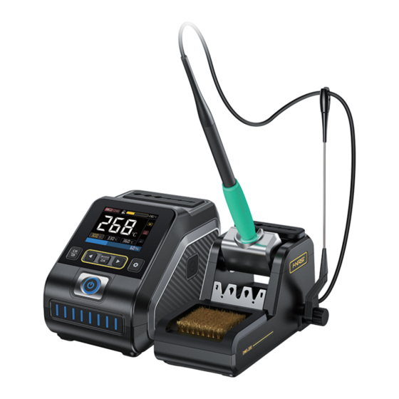
2.Product Features ●HD color screen, intelligent control ●Adaptive wide voltage (110-250V) input ●Maximum power of 200W, rapid heating ●Multiple preset groups, convenient and fast ●Supports F245, F210 type handles, strong compatibility ●Real-time hibernation mode to extend soldering iron tip life ●Multiple mode real-time monitoring of power and temperature status 3.Structure Introduction and Wiring Diagram 3.1 Host introduction... - Page 6 Type-C firmware upgrade interface Power switch Hibernate Holder Connection Hole Power supply interface Input fuse Soldering station handle interface...
- Page 7 3.2 Introduction to hibernation seat Handle wire clip Soldering iron tip placement area Handle Hibernator seat Soldering iron tip plug socket Steel wire cleaning area Hibernate holder connection hole...
-
Page 8: Wiring Diagram
3.3 Wiring diagram Host power wiring Host soldering iron handle wiring After the power cord is connected, if After inserting the handle into the you need to disconnect the power interface, make sure to use the knob you can do so by toggle the power to lock it again to prevent the switch to operate. -
Page 9: Panel Introduction
4.Panel Introduction Temperature Handle model adjustment F��� ℃ Audio prompts Real-time temperature Operating status ℃ Temperature lock indication Quick presets ℃ ℃ ℃ Power bar indication F��� ℃ ℃ ℃ ℃ ℃ Temperature curve thumbnail F��� CurrentTempe ℃ ℃ ��� ���... - Page 10 5.Work Process Description F��� ℃ in standby Current tempe ℃ Pick up the soldering iron or press in sleep ℃ ℃ ℃ left until standby any button to star t heating Power-on page Hibernate page Standby page Main interface Connect the devices according to the wiring diagram, turn on the power switch on the back of the main unit, and press the power button briefly to turn on the device.
-
Page 11: Heating Status
Entering the main interface, the soldering iron is in normal working condition, divided into the following four states: Heating status: In this state, the F��� ℃ second icon on the right side of the status bar will change to a heating Heating icon. - Page 12 Shutdown/Power on state:Press the power button briefly to shut down/power on. Notice Do not touch the hot parts when the soldering iron is in the heating or heated and ready to use state. 6.Operating instructions 6.1 Host introduction Power on: The screen displays the boot icon, then automatically transitions to the hibernation page or main page (if the soldering iron tip is picked up during the boot process, it will automatically transition to the main page, otherwise the...
- Page 13 Current tempe in sleep left until standby Power on page Hibernate page F��� ℃ ℃ Please insert the soldering iron tip ℃ ℃ ℃ Main interface Prompt to insert soldering iron tip Homepage switch: There are three pages on the main interface, press the MODE button briefly to switch between pages.
- Page 14 Target temperature setting: You can set the target temperature on all three main pages in two ways. ①Pressing briefly or holding down the button can both set the target tempera- ture. When in heating mode, pressing the button sets the target temperature, and when in hibernation mode, pressing the button sets the hibernation temperature.
-
Page 15: Basic Menu Operations
6.2 Basic menu operations Accessing the first-level settings Return to the main page: When on page: press the key briefly to the first-level settings page, press enter the temperature settings page. key briefly to return to the main page. Tempe set F���... - Page 16 6.3 Temperature Setting Temperature increment: Press the Tempe set key briefly to select, after which a triangle Tempe step symbol will appear. Press the key briefly or long press to adjust the ℃ increment value. Press the key again Tempe lock to save the setting.
-
Page 17: Standby Switch
Standby switch: After selecting the standby Sleep set switch, simply short press the key to Sleep tempe Standby switch turn it on or off. When the standby switch is ��� ℃ activated, the screen will display the standby screen when entering the standby screen off Screen shutdown Standby time ��... -
Page 18: Temperature Calibration
6.6 Temperature calibration Temperature calibration 150/250/350: Tempe calibration After selecting the temperature that needs ��� ��� ��� to be calibrated, press the key to enter ℃ ℃ ℃ calibration mode. Place the soldering iron tip on the calibration device, and once the temperature stabilizes, press or hold the After selecting the corresponding tem perature gear, place the soldering iron... -
Page 19: Temperature Unit
Temperature unit ℃/℉: After selecting the System settings temperature unit, press the key briefly Brightness to switch between ℃ and ℉. Volume Tempe unit ℃ ℉ 6.8 System language Switch language:by pressing the System language key, then press to confirm and switch. -
Page 20: Firmware Upgrade
Please drag the firmware interface, wait for the USB flash drive to pop file to USBflash disk! up and copy the firmware file to the USB flash drive. 8.Product Parameters DWS-200 Model Number 200W (MAX) Power 100—450℃ Temperature Range L 156 x W 96 x H 103 (in mm) - Page 21 9.Soldering Iron Tip Replacement and Cleaning 9.1 Replace the soldering iron tip 1.Use the plug-in holder to separate the soldering pen from the soldering iron tip. 2.Use the plug-in holder or bare hands to insert the new soldering iron tip Insert the new soldering iron tip into the handle.
- Page 22 9.2 Cleaning of soldering iron tips Using a high-density fine copper wire brush can effectively clean the soldering iron tip while also providing protection for the tip. 10.Soldering Iron Tip Use and Maintenance ①After the temperature stabilizes, use a clean sponge to clean the soldering tip and check the iron's condition.
- Page 23 10.1 Use of soldering iron tips Excessive temperature will weaken the functionality of the soldering iron tip, so it is recommended to use the lowest possible Soldering iron temperature setting. This soldering iron tip has excellent temperature recovery, head temperature seat allowing for sufficient soldering at lower temperatures to protect temperature-sen- sitive components.
-
Page 24: Production Information
●The solder or iron plating is impure, or the soldering surface is not clean. 11.Production Information Any FNIRSI'users with any questions who comes to contact us will have our promise to get a satisfactory solution + an Extra 6-Month Warranty to... - Page 25 下载用户手册&应用软件 Download User manual&APP&Software...
Need help?
Do you have a question about the DWS-200 and is the answer not in the manual?
Questions and answers
kann man damit kabel mit einem kabelquerschnitt von 6mm2 an einen Stecker(XT90) löten?