Table of Contents
Advertisement
Quick Links
Owner's Instruction and Operation Manual
Model Number:
DVP08
Report Number: F23-147
Certified to ANSI STD Z21.86-2016-R-2021,
Certified to CSA STD 2.32-2016-R-2021, and
Certified to CSA 2.17-2017
* All Pictures In This Manual Are For Illustrative Purposes Only. Actual Product May Vary.
Save These Instructions In A Safe Place For Future Reference.
WARNING: If the information in these instructions is not followed exactly, a fire or explosion may result
- Do not store or use gasoline or other flammable vapors and liquids in the vicinity of this or any other
appliance.
- WHAT TO DO IF YOU SMELL GAS:
•
Do not try to light any appliance.
•
Do not touch any electrical switch; do not use any phone in your building.
•
Immediately call your gas supplier from a neighbor's phone. Follow the gas supplier's instructions.
•
If you cannot reach your gas supplier, call the fire department.
- Installation and service must be performed by a qualified installer, service agency or the gas supplier.
* Installation and service must be performed by a qualified installer, service agency or the gas supplier *
Please read this manual BEFORE
installing and operating this unit.
INSTALLER: Leave this manual with the appliance.
CONSUMER: Retain this manual for future reference.
THIS MANUAL IS SUBJECT TO CHANGE WITHOUT NOTICE.
World Marketing of America, Inc, 12256 William Penn Hwy, Mill Creek, PA 17060
• DVN08
R
causing property damage, personal injury or loss of life.
PH: 1-800-776-9425 Email: info@worldmkting.com
CALIFORNIA PROPOSITION 65 WARNING:
This product can expose you to chemicals including carbon
monoxide, which is known to the State of California to cause
cancer, birth defects, and/or other reproductive harm. For
more information, go to
854103-1203N
www.P65warnings.ca.gov
Advertisement
Table of Contents

Summary of Contents for World Marketing of America Comfort Glow DVP08
- Page 1 For CONSUMER: Retain this manual for future reference. more information, go to www.P65warnings.ca.gov THIS MANUAL IS SUBJECT TO CHANGE WITHOUT NOTICE. World Marketing of America, Inc, 12256 William Penn Hwy, Mill Creek, PA 17060 PH: 1-800-776-9425 Email: info@worldmkting.com...
-
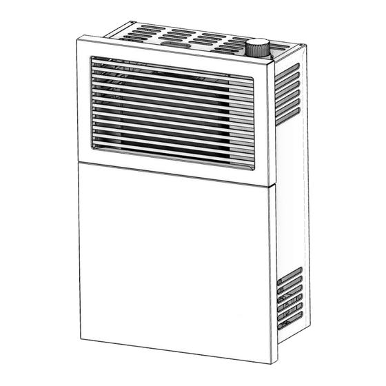
Page 2: Product Features
DIMENSIONS Height 20 (508 mm) Width 13.6 (346 mm) Depth 6.6 (169 mm) Type of Burner Atmospheric # of Burners Ignition Piezo-electric ignitor Standard Heating Space 280 sq ft (26 m Square Feet / (m NOTE: A qualified service person must install the heater. -
Page 3: Installation Checklist
INSTALLATION CHECKLIST Your Gas Stove should be installed by a qualified installer only. An NFI qualified Installer can be found at www.nficertified.org/public/find-an-nfi-pro/ INSTALLER CHECK LIST This Checklist is to be completed in full by the qualified person who installs this unit. Keep this page for future reference. - Page 4 MASSACHUSETTS RESIDENTS REQUIREMENTS FOR THE SIGNAGE COMMONWEALTH OF A metal or plastic identification plate shall be MASSACHUSETTS permanently mounted to the exterior of the building at a minimum of eight (8) feet above The following requirements reference various grade directly in line with the exhaust vent terminal Massachusetts and national codes not contained for the horizontally vented gas fueled heating the in this manual.
-
Page 5: Product Identification
MASSACHUSETTS RESIDENTS referenced “special venting systems” A copy of all installation instructions for all Product instructions shall be included with the appliance or Approved side wall horizontally vented gas fueled equipment installation instructions and; equipment, all venting instructions, all parts lists for venting instructions, and/or all venting design The “special venting systems”... -
Page 6: Installation Items
INSTALLATION INSTALLATION ITEMS Minimum Clearance From Combustible Before installing heater, make sure you have the Construction items listed below. Rear 0.25 inches (with supplied spacers) • Piping (check local codes) Sides 6 inches • Sealant (resistant to propane gas) 36 inches •... - Page 7 INSTALLATION IN S ID T A IL E R D E C O R N F IX E D C L O S A B LE O P E R F IX E D C L O S A B LE O P E R VENT TERMINAL AIR SUPPLY INLET...
-
Page 8: Installing The Appliance
INSTALLATION INSTALLING THE APPLIANCE IMPORTANT: Separate the hanging bracket from the appliance INSTALLATION REPAIR SHOULD by removing two screws on the top and two nuts at DONE BY A QUALIFIED SERVICE PERSON. the bottom. THE APPLIANCE SHOULD BE INSPECTED BEFORE USE AND AT LEAST ANNUALLY INSTALLING THE HANGING BRACKET BY A QUALIFIED SERVICE PERSON. - Page 9 INSTALLATION INSTALLING THE HANGING BRACKET Figure 3a ON A COMBUSTIBLE WALL (I.E, DRYWALL/WOODEN WALL) Remove the required heat shield from the box and fold it as indicated in the illustration (fold along the perforated lines and break off when installing in a 2 X 4 wall). Align the holes on the heat shield with the holes on the mounting bracket and attach using the six provided small screws (vi).
- Page 10 INSTALLATION 2. Taking into account the minimum clearances 5. Insert the two provided rubber grommets (v) mentioned in table two, locate the closest wall into the lower bracket as shown. stud (which will serve to hold the appliance) and mark the square hole center at a distance “A”, (if wall stud is at the right), or “B”, (if the stud is at the left) (see table 2 and Figures 7 and 8).
-
Page 11: Installing The Venting System
INSTALLATION ATTENTION: THE ATTACHED SET OF THREE MARKING PLATES (RATING PLATE, OPERATION INSTRUCTIONS, AND SAFETY PLATE) MUST NOT BE REMOVED FROM THE APPLIANCE AT ANY TIME. MOUNTING THE HEATER ON HANGING BRACKET Place the heater on the hanging bracket and secure with two small screws (vi). - Page 12 INSTALLATION Minimum of IMPORTANT: 4-1/2” (115 mm) THE APPLIANCE’S VENTING SYSTEM SHOULD Wall Thickness BE INSPECTED AT LEAST ONCE A YEAR AND IMMEDIATELY CLEANED IF NECESSARY. Maximum of CAUTION: 10” (254 mm) Wall Thickness ALL JOINTS MUST BE AIR-TIGHT. The venting system consists of: Figure 7 Vent Cap Vent Pipe...
-
Page 13: Gas Connection
INSTALLATION 11. Hand-bend the rain shield (J) into a semi-circle and align it with the mounting holes located Rod (D) in the outdoor mounting plate (F). Secure the rain shield (J) to the outdoor mounting plate (F) using three (3) small screws (vi) included in the Vent-Air hardware packet. -
Page 14: High Altitude Installations
INSTALLATION PRESSURE TESTING SUPPLY LINE ATTENTION: This appliance and its appliance main APPLIANCE GAS INLET gas valve must be disconnected from the gas 3/8” NPT PIPE NIPPLE supply piping system during any pressure testing GROUND JOINT OPEN of that system at test pressures in excess of 1/2 psi MANUAL SHUTOFF UNION (3,5 kPa). -
Page 15: Operation
OPERATION WARNING: IF YOU DO NOT FOLLOW THESE INSTRUCTIONS EXACTLY, A FIRE EXPLOSION MAY RESULT CAUSING PROPERTY DAMAGE, PERSONAL INJURY OR LOSS OF LIFE. LIGHTING INSTRUCTIONS 1. STOP! Read the safety information on the POSITION INDICATOR attached plate. 2. Ensure the gas supply to the heater is on. 3. -
Page 16: For Your Safety Read Before Lighting
OPERATION FOR YOUR SAFETY READ BEFORE 2. Ensure the gas supply to the heater is on. LIGHTING 3. Slightly push down the gas control knob and turn it clockwise to the “OFF” position. Do not WARNING: force. NOTE: The knob cannot be turned from “PILOT”... -
Page 17: Cleaning And Maintenance
OPERATION IMPORTANT: • DO NOT DRY CLOTHES OVER THE HEATER. • DO NOT SPRAY ANY AEROSOL NEAR THE HEATER WHEN FUNCTIONING. DO NOT STORE THESE ELEMENTS NEAR THE APPLIANCE. • DO NOT TOUCH GRILL TO AVOID BURNS. • AVOID BLOCKING AIR INLET AND HOT AIR OUTLET. •... - Page 18 OPERATION CLEANING THE MAIN BURNER ORIFICE SECONDARY FLAME PRIMARY FLAME & MAIN BURNER Turn OFF gas supply to the heater. 2. Remove casing assembly. 3. Disconnect burner tubing and remove orifice holder. THERMOCOUPLE 4. Apply compressed air to the orifice holder assembly to remove dust, lint or spider webs.
-
Page 19: Troubleshooting
TROUBLESHOOTING WARNING: TURN OFF HEATER AND LET COOL BEFORE SERVICING. ONLY A QUALIFIED SERVICE PERSON SHOULD SERVICE AND REPAIR HEATER. PROBLEM POSSIBLE CAUSE REMEDY Ignitor electrode broken. Replace ignitor electrode. Ignitor electrode not connected to When ignitor Reconnect ignitor cable. ignitor cable. - Page 20 TROUBLESHOOTING PROBLEM POSSIBLE CAUSE REMEDY Heater produces a clicking/ticking Metal expanding while heating or This is common with most heaters. If noise is noise just after contracting while cooling. excessive, contact qualified service person. burner is lit or shut off. Low line pressure.
-
Page 21: Replacement Parts
REPLACEMENT PARTS... - Page 22 REPLACEMENT PARTS Part # Description Vent Pipe Kit (Includes inner/ 893984 outer pipe, vent cap, hardware) 894008 Rain Shield 88370 Silicone Seal 893978 Outdoor Mounting Plate 28994 Shield 893952 Wall Bracket 893999 Control Knob 81367 Burner Tube Connection 81368 Regulator Connection Tube 81307 Gas Regulator (NAT) 81308...
- Page 23 The operation of this unit in a manner inconsistent with the owner’s manual will void the warranty and is also against federal regulations. World Marketing of America, Inc. warrants this product to be free from defects in material and workmanship, to the original retail purchaser only, and for the time period identified above, measured from the date of the initial purchase as evidenced on an invoice, cancelled check, sales receipt, etc., to receipt of a claim by World Marketing of America, Inc.
- Page 24 • Replace the defective part free of charge. Parts and/or service replacements made under the terms of this warranty are warranted only for the remaining period of the original heater warranty. • Replace the heater free of charge. Should the heater be replaced by World Marketing of America, Inc. “free of charge”, all further warranty obligations are thereby met.
-
Page 25: Service Record
SERVICE RECORD It is recommended that your heating system is serviced regularly and that the appropriate Service Interval Record is completed. SERVICE PROVIDER Before completing the appropriate Service Record below, please ensure you have carried out the service as described in the manufacturer’s instructions. Always use the manufacturer's specified spare part when replacement is necessary. - Page 26 NOTES...
- Page 27 NOTES...
Need help?
Do you have a question about the Comfort Glow DVP08 and is the answer not in the manual?
Questions and answers