Table of Contents
Advertisement
Quick Links
The functionality of the instrument may be impaired if the system is used
The present manual is an accessory part of the LCT-18. Please retain these
QBIT Srl
via La Farina 47
50132 Firenze - ITALIA
sales: +39.340.8213168
tech: +39.393.8327765
qbit@libero.it
www.qbit-optronics.com
LCT-18
INSTRUCTION MANUAL
in a manner not specified in this manual.
instructions for future reference.
NOTICE
NOTICE
1
Advertisement
Table of Contents
Troubleshooting

Summary of Contents for QBIT LCT-18
- Page 1 The functionality of the instrument may be impaired if the system is used in a manner not specified in this manual. NOTICE The present manual is an accessory part of the LCT-18. Please retain these instructions for future reference. QBIT Srl...
-
Page 2: Table Of Contents
TABLE OF CONTENTS GENERAL NOTICES ........... . . FOREWARD. - Page 3 V.6. QBIT APPLICATION FOR LCT-18........
- Page 4 TABLE INDEX Table II.1 – Measurement specifications ......... . . 9 Table II.2 –...
-
Page 5: General Notices
4. WARRANTY QBIT s.r.l. warrants that, at the time of delivery, this product is free from defects or malfunctions, and it conforms substantially to the specifications reported in the present manual. QBIT’s liability is limited to... - Page 6 QBIT’s option, of this product or parts thereof returned to seller and shown to QBIT’s reasonable satisfaction to have been defective; provided that written notice of the defect shall have been given by Buyer to QBIT within one (1) year after the date of delivery of this product by QBIT.
-
Page 7: Chapter I - Safety
CHAPTER I SAFETY Safety is essential in the use and maintenance of the equipment. Therefore the present chapter provides important safety information concerning the operation and maintenance of the LCT-18 system. I.1. GENERAL SAFETY The system LCT-18 is consistent with the following directives: - CE Council Directive 2006/95/EC (Electrical safety of low voltage equipment);... -
Page 8: Cleaning
I.2. 5. Cleaning: Use a dry cloth to clean the outside of the case. Do not use soap and water. Do not use blast of compressed air. When the system is not in use, it is suggested to protect the sniffer tip with its plastic cap and set the equipment in a dry, dust free place. -
Page 9: Chapter Ii - Specifications
CHAPTER II SPECIFICATIONS II.1. MEASUREMENT SPECIFICATIONS: The measurement specifications are reported in Table II.1. Table II.1 Detectable gases ..Measuring head LS-3... .CO Measuring head LS-4. -
Page 10: Ii.3. Technical Terms
CALIBRATED LEAK: certified device reproducing a leak of known gas type and rate (optional). II.4. DISPOSAL At the end of lifetime, the system is to be disposed as electronic material, following European Directives 2002/95/EC e 2003/108/EC. The Buyer will contact QBIT s.r.l. to get any instruction about disposal or return of the equipment. -
Page 11: Chapter Iii - Functional Overview
CHAPTER III FUNCTIONAL OVERVIEW The system LCT-18 is a refrigerant gas leak detector for industrial applications. It was studied to allow detection and measurement of very small leaks that may occur in any field or device where specified gases (see Table II.1) are employed. The state-of-the-art detection method, based on infra-red light absorption, leads to high sensitivity, short response time, reduced ownership costs and long lifetime. -
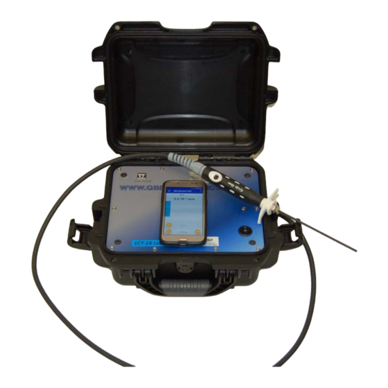
Page 12: Iii.1.1. Main Switch
Figure III.1. Main panel. III.1.1. Main switch The electric power can be switched ON and OFF by means of the black switch located on the main panel (right side). III.1.2. Identification plate On top of main panel, the instrument identification plate reports the model and the serial number. III.1.3. -
Page 13: Iii.2.1. Fan
Figure III.2. Rear panel. III.2.1. Fan The rear panel fan allows continuous flow of external air in order to assure the correct operation of the leak detector. III.2.2. Power supply / battery connector The screw socket is used for connecting the external power supply to the battery. III.3. -
Page 14: Iii.6. Accessories
Figure III.3. 1) Capillary sniffer , 2) handpiece. III.6. ACCESSORIES III.6.1. Battery charger Figure III.4 shows the external power supply/battery charger. The power supply is equipped with a warning light which is red when electrical current is supplied and becomes green if no current is delivered. -
Page 15: Iii.6.2. Sniffer Filters And Velcro Strips
Figure III.5: Tip filters for sniffer and self-adhesive Velcro strips. III.6.3. Manual The present operating manual is an accessory of LCT-18. Retain these instructions for future reference. Electronic version of any technical document is also available at the URL www.qbit-... -
Page 16: Chapter Iv - Preparing For Operation
Temperature changes usually induce fluctuations in the measure of background concentration. Although the LCT-18 has been studied and manufactured so that it has the best temperature stability, it is suggested to install the detector in a place whit minimum temperature variations. -
Page 17: Chapter V - System Functionality
CHAPTER V SYSTEM FUNCTIONALITY V.1. POWER SUPPLY CONNECTIONS V.1.1. Connection to external AC line The link to an external AC line is obtained through the external power supply/battery charger shown in Figure V.1. Connect the male and female black/blue connectors and tighten the safety nut. Figure V.1. -
Page 18: Before Turn-On
When the main unit is switched on the rear panel fan and the internal pump are also activated. V.5. INSTALLATION AND SW START-UP The QBIT application (Figure V.3) is factory pre-installed in the phone/tablet, and the start icon is in the application bar of the desktop (Android or Windows). It is possible to down-load the software from... -
Page 19: Qbit Application For Lct-18
Windows), or in the desktop start-menu bar. In order to enter the instrument control window it is sufficient to launch the application. The Qbit software presents a simple and friendly graphic interface. The full SW description is also available at the following URL... -
Page 20: Initial Pairing
V.7. INITIAL PAIRING In case the control unit has not yet configured (e.g. a phone not supplied by QBIT), it is necessary to establish the initial pairing among the control unit and the main unit (suit-case). Turn on both the devices and verify they are in a range of distance suitable for Blue-Tooth connection. -
Page 21: External-Leak Calibration
If the external-leak calibration is correctly performed, the LCT-18 will detect the leak with a value corresponding to the nominal one. The factory calibration can be easily restored by accessing the application sub-menù... -
Page 22: Chapter Vi - Errors And Troubleshooting
CHAPTER VI ERRORS AND TROUBLESHOOTING VI.1. SYSTEM ERRORS AND MALFUNCTIONS The system is equipped with auxiliary sensing devices to reveal errors and malfunction conditions. As soon as any malfunction occurs, the corresponding alarm message is displayed on the control unit screen. -
Page 23: Vi.2.3. Abnormal Reference Level
VI.2. 3. Abnormal reference level If the message “WARNING Calibration took place in a pollute environment…..“ is displayed on the main screen, the last auto-zero procedure occurred in a polluted environment. Repeat the zero procedure, paying attention that the sniffer is placed in a clean, not polluted area. VI.2. -
Page 24: Vi.3. Troubleshooting
VI.3. TROUBLESHOOTING In Table VI.1, the most frequently occurring errors and malfunctions are reported, together with any user countermeasure:... - Page 25 Table VI.1 Malfunction What to do Turn-on fails Check that the power cord is connected and AC required specifications are met. Verify the fan on the rear panel and the led on the battery charger. If the fan and the led are off the power supply is not properly working.
-
Page 26: Chapter Vii - Maintenance
CHAPTER VII MAINTENANCE For a long and reliable operation of the LCT08 infrared detection system, a few maintenance operations are suggested to be performed by the user and by qualified personnel. VII.1. USER MAINTENANCE VII.1.1. Cleaning suggestions Daily cleaning - remove dust and solid particles from the instrument; - do not use abrasive products;... -
Page 27: Vii.2. Qualified Personnel Maintenance
Figure VII.1: 1) Filter , 2) handpiece, 3) sniffer. Unscrew the sniffer by using 12 mm and 14 mm wrenches. Remove the filter placed in the sniffer connector (Figure VII.1). Verify that the stainless steel capillary is not obstructed and insert the new filter. -
Page 28: Chapter Viii - Accessory Parts
CHAPTER VIII ACCESSORY PARTS VIII.1. SYSTEM ACCESSORY PARTS The leak detector is supplied with the following accessory parts: - n. 20 paper filters - battery charger with AC power cord - self adhesive Velcro strips - operation manual...
Need help?
Do you have a question about the LCT-18 and is the answer not in the manual?
Questions and answers