Advertisement
Order Codes
TEX-CTR10
-HV 85-265V AC / 95-370V DC
-LV
15-48V AC / 10-72V DC
Options
-A
1 x mA/V analog output
-S2R 1 x RS232 (RJ11 terminal)
-S4S 1 x RS485 (screw terminal)
Copyright © 2013 Defi ne Instruments
TEX-CTR10
TEX-CTR10
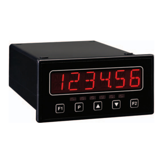
Counter Indicator
Counter Indicator
The TEX-CTR10 indicator is the ideal so-
lution for a variety of counting and rate
application requirements.
This meter has been designed for ease
of use, with intuitive, scrolling text
prompts that guide you step-by-step
through the setup process.
The front panel includes a 6 digit LED
display and five front panel buttons, for
simple operator interface.
One of the five buttons is user-pro-
grammable, so you can customise it as
a shortcut to your most frequently used
feature.
Contents
1 - Specifi cations ............................. 2
2 - Casing & Display ........................ 3
3 - Wiring ......................................... 5
4 - Input Setup & Calibration ......... 9
5 - Reset PIN Number ...................... 15
Confi guration ............................. 16
Appendix B - Serial Modes ............. 17
TEX-CTR10-MAN-13V03 (0819)
1
Advertisement
Table of Contents

Related Manuals for Define Instruments TEX-CTR10

Summary of Contents for Define Instruments TEX-CTR10
-
Page 1: Table Of Contents
TEX-CTR10 TEX-CTR10 Counter Indicator Counter Indicator The TEX-CTR10 indicator is the ideal so- lution for a variety of counting and rate application requirements. This meter has been designed for ease of use, with intuitive, scrolling text prompts that guide you step-by-step through the setup process. -
Page 2: Specifications
Rate resolution 0.01Hz (1Hz with high speed mode on - see 4.3F to enable) Rate accuracy 0.005% Rate temperature drift Typically 2ppm/°C Input noise fi ltering 20kHz, 2kHz, 200Hz or off Security Setup PIN code protected for security TEX-CTR10-MAN-13V03 (0819) Copyright © 2013 Defi ne Instruments... -
Page 3: Casing & Display
Dimensions 48H x 96W x 120D (mm). When calculating space requirements, please allow 30-50mm clearance behind the unit for connectors and wiring. Panel cutout 45H x 92W (mm) Display 1 x 6 digit (13mm), 14 segment alphanumeric LED 96 mm 120 mm Copyright © 2013 Defi ne Instruments TEX-CTR10-MAN-13V03 (0819) - Page 4 BRI appears and toggles with the current setting. Use the buttons to adjust the LED backlight, and then press to return to the normal operating mode. TEX-CTR10-MAN-13V03 (0819) Copyright © 2013 Defi ne Instruments...
-
Page 5: Wiring
Advanced users may remove the input module from its enclosure and re-adjust the header settings. See Appendix A for more information. Wire your input as shown in the appropriate diagram overleaf. See 3.1D Copyright © 2013 Defi ne Instruments TEX-CTR10-MAN-13V03 (0819) - Page 6 + 24V EXC + Supply a separate +5V power supply Supply -- Supply Namur sensor SIGNAL › Active sensor signal: 0.3-1.0mA NAMUR + 24V EXC SENSOR › Inactive sensor signal: 1.7 - 3.0mA TEX-CTR10-MAN-13V03 (0819) Copyright © 2013 Defi ne Instruments...
- Page 7 User 1: User defined function (see 4.5C) › Inhibit: Prevents the totalizer from counting › Test: Resets the unit User 1 Inhibit Test User 2 › User 2: User defined function (see 4.5D) See 3.1E Copyright © 2013 Defi ne Instruments TEX-CTR10-MAN-13V03 (0819)
- Page 8 HV power LV power See 3.1F supply supply Once you have completed the wiring process it is safe to switch on your power supply. Ensure that your display is functioning before you proceed. TEX-CTR10-MAN-13V03 (0819) Copyright © 2013 Defi ne Instruments...
-
Page 9: Input Setup & Calibration
4.2C) scrolls across the display and toggles with the selected display value. Adjust this value as required using the buttons, and press E.g. If you set 1,500 pulses in 4.2C, and 1,500 pulses = 1 metre, then enter 1 here. Copyright © 2013 Defi ne Instruments TEX-CTR10-MAN-13V03 (0819) - Page 10 The instrument will automatically calculate the required scale factors based on the input channel setup, so you must complete 4.2 fi rst. TEX-CTR10-MAN-13V03 (0819) Copyright © 2013 Defi ne Instruments...
- Page 11 However, increasing the window size too far will reduce the ability of the instrument to respond quickly to real changes in input signal. Setting AVE WINDOW to 0 will give continuous averaging as per the selected averaging samples. Copyright © 2013 Defi ne Instruments TEX-CTR10-MAN-13V03 (0819)
- Page 12 _ _ _ USER INPUT 2 scrolls across the display and toggles with the function to be executed when the User 2 input pin is activated (see 3.5). Use the buttons to make a selection (referring to the table above), and then press TEX-CTR10-MAN-13V03 (0819) Copyright © 2013 Defi ne Instruments...
- Page 13 _ _ _ CAL HIGH ANALOG OUTPUT scrolls across the display and toggles with a calibration number displayed in internal units (mA or V). Using the buttons, calibrate your high analog output as required, and then press Copyright © 2013 Defi ne Instruments TEX-CTR10-MAN-13V03 (0819)
- Page 14 The serial address of the controller must be set to match the serial address defi ned in the master device. Refer to Appendix B for more information on serial modes and registers. TEX-CTR10-MAN-13V03 (0819) Copyright © 2013 Defi ne Instruments...
-
Page 15: Reset Pin Number
When successful, a factory identifi cation text will scroll across the display, fol- lowed by – PIN NUMBERS RESET TO 1 Reset the default PIN number if required by following the instructions in 4.8, entering ‘1’ whenever you are prompted for your current PIN. Copyright © 2013 Defi ne Instruments TEX-CTR10-MAN-13V03 (0819) -
Page 16: Appendix A - Input Header Configuration
Suitable for a noisy signal 20KHz Suitable for a noisy signal Load (D) SINK NPN, TTL & pushbuttons Mode (B) SOURCE Counter Always use this setting NAMUR Namur FREQ Not used for TEX-CTR10 TACH Tacho TEX-CTR10-MAN-13V03 (0819) Copyright © 2013 Defi ne Instruments... -
Page 17: Appendix B - Serial Modes
-1000000 to 1000000, but please note that not all registers will accept this range. Message Terminator - This is the last character, and must be either a '$' (dollar) or an '*' (asterisk). Neither of these characters should be used elsewhere in the Copyright © 2013 Defi ne Instruments TEX-CTR10-MAN-13V03 (0819) - Page 18 Modbus (RTU) is an industry standard RTU slave mode that allows connection to a wide range of devices. Modbus registers are all holding registers, and should be ac- cessed via function codes 3 and 6. TEX-CTR10-MAN-13V03 (0819) Copyright © 2013 Defi ne Instruments...
- Page 19 (If there is no decimal point, then the fi rst character is a space. Leading zero blanking applies.) Status - Single character output value status. 'U'=Under, 'O'=Over, 'E'=Error. End - ETX character (ASCII 03) Copyright © 2013 Defi ne Instruments TEX-CTR10-MAN-13V03 (0819)
- Page 20 10B Vega Place, Mairangi Bay, Auckland 0632, New Zealand PO Box 245 West Harbour, Auckland 0661, New Zealand Ph: +64 (9) 835-1550 | Aus: 1800 810-820 | Fax: +64 (9) 835-1250 www.defi neinstruments.com TEX-CTR10 MV1.2 Revision Code: TEX-CTR10 -MAN-13V03 Date Code: 120819...
Need help?
Do you have a question about the TEX-CTR10 and is the answer not in the manual?
Questions and answers