Table of Contents
Advertisement
Quick Links
Advertisement
Table of Contents

Summary of Contents for MASHPROJECT MF-71L
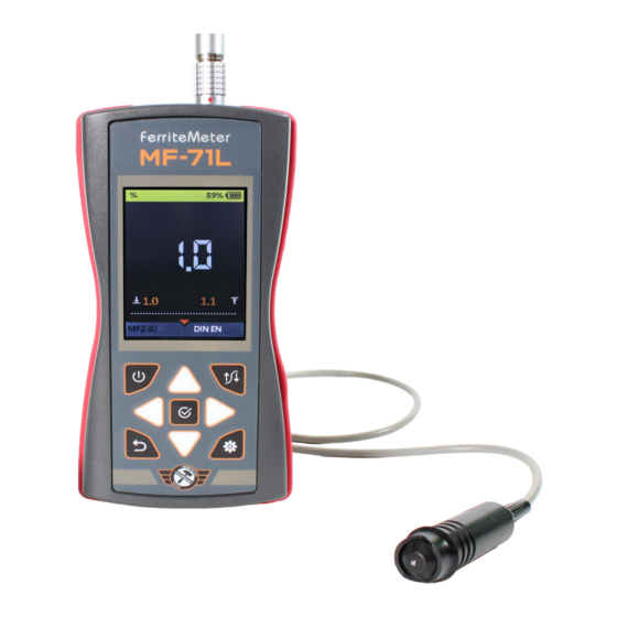
- Page 1 Ferrite meter MF-71L Operation manual...
-
Page 2: Table Of Contents
Ferrite meter MF-71L Contents: 3 Maintenance 1 General 3.1 Prevention measures 1.1 Intended use 3.2 Battery 1.1.1 Field of application 3.3 Battery charging 1.1.2 Operation conditions 3.4 Trouble shooting 1.2 Delivery set 1.3 Specifications 4 Storage 1.4 Principal and structure 5 Transport 1.4.1 Structure... -
Page 3: General
1.1 Intended use 1.1.1 Field of application The MF-71L ferrite meter is designed to measure the percentage of ferrite phase in steel samples. It can be used in laboratory, field and workshop conditions at enterpris- es of mechanical engineering, energy, radio electronics and other industries. - Page 4 Name, type Quantity Electronic unit 1 pc. Magnetic induction probe 1 pc.* Ferrite phase content control specimen 1 pc. USB А – micro USB cable 1 pc. Charger 1 pc. Carrying bag 1 pc. User manual 1 copy Calibration certificate 1 copy Table 1 * Number and type of probes are on customer’s request.
-
Page 5: Specifications
1.3. Specifications The main metrological and technical characteristics are given in Table 2. Parameter Magnetic induction probe Measurement range 0 – 100 % ± (0.03 d + 1), where d is the percentage Limits of absolute measurement error of the measured ferrite phase content) Resolution in the measurement range of 0,1% 5 …... -
Page 6: Principal
1.4.2 Principal The operating principle of the ferrite meter is based on recording the electromotive force (EMF) arising in the winding of a differential-type magnetic induction probe when it is placed on a magnetic or non-magnetic base of the test object. The level of EMF depends on the size of the gap between the probe working part of the and the base. - Page 7 Arrows are used to select and change active parameters. Their actions are similar for different operating modes and are designed for intuitive learning, since their symbols correspond to the nature of their action. Probe socket Power adapter USB port MF-71L Ferrite meter...
-
Page 8: Operation
2. Operation 2.1 Operating limitations The device is intended for operation in the environmental conditions specified in para- graph Error: Reference source not found. 2.2 Getting ready to work 2.2.1 Probe connection Magnetic induction probes are used to determine the percentage of ferrite phase or ferrite number. - Page 9 The SETUP mode menu is shown in Fig . The name of current configuration is dis- played in the top information line. Figure 5 The functions of the buttons in SETUP mode are given in Table Table 4 Button Function Navigate through menu items Enter the selected item settings Exit SETUP mode...
- Page 10 Table 3 Menu item (parameter) Parameter value Description Selection the measurement Mode discrete / continuous method Units of Selection of units of % / FN measurement measurement from 0 to 100 (%) from 0 Limits Setting the operation thresholds to 120 (FN) Starting adjustment Adjustment procedure using one...
- Page 11 Table 4 Button Function Changing the parameter value Navigate through menu items Exit with confirmation of the changes made Return the previous menu (all changes made will be saved) 2.3.2.1. Mode This menu item allows to select the measurement mode: The DISCRETE mode is the main operating mode of the device providing obtaining measurement results in the selected units (percentage or ferrite number) over the entire range of measured values.
- Page 12 Figure 6 Measurement history Max value Min value Standard deviation Arithmetic mean Number of measurements taken...
- Page 13 The CONTINUOUS mode displays the current value of the ferrite phase percentage or ferrite number in real time when scanning over the test object and ensures that the result is updated at least four times per second. This mode is intended for monitoring special areas of test object and for comprehensive testing of the device performance.
- Page 14 2.3.2.3 Limits This menu item allows to set up the upper and the lower limits of operation threshold or specify the operation threshold range. Acceptable values range from 0 to 100%. The LIMITS menu is shown in Figure 9.
- Page 15 2.3.2.4 Adjustment This menu item is intended to adapt the device to the connected probe and additional calibration setup. The adjustment procedure allows to save only one point. Otherwise, the adjustment procedure is similar to the calibration procedure described in paragraph. The ADJUST- MENT menu is shown in Figure 10.
- Page 16 ATTENTION: WHEN RESETING THE CALIBRATION RESULTS, THE ADJUSTMENT RE- SULT WILL ALSO BE RESET! 2.3.2.5 Calibration This menu item is intended to perform device calibration using ferrite phase content control specimens included in the delivery set or using a representative area of the test object.
- Page 17 • proceed to calibration using control specimens (see Figure 12. ) At all stages of calibration using control specimens, buttons are displayed on the screen. Use buttons to navigate. When button is selected and button is pressed, all measurement results will be reset. When button is selected and button is pressed, the current calibration result will be saved as the default value (set to default - reset calibration).
- Page 18 Note – It is necessary to perform from 4 to 6 measurements to carry out the subsequent manual correction of the calculated average value. • after the fourth measurement, additional arrows will appear above and below the average value, indicating that its manual correction is available (see Figure 15.
- Page 19 2.3.2.6 Configuration The device has a preset BASIC configuration by default. Separate configurations can be created for saving and further use of different sets of parameters or probe types or test objects. The functions of the buttons active in this menu item are given in Table 5. buttons to navigate.
- Page 20 2.3.2.7 Language Selecting the device interface language: • English • German The LANGUAGE menu is shown in Figure 18. 2.3.2.8 Energy saving Menu item (parameter) Parameter value Description Automatic shutdown time, 0,5 / 1 / 2 / 3 / The period of time after which the minutes 4 /5 device will turn off automatically,...
-
Page 21: Discrete Mode
2.3.2.9 Turning off 2.3.3 DISCRETE mode Switching off the device. In the DISCRETE mode, separate meas- The DISCRETE mode menu is shown in urements are carried out each time the Figure 20. probe is placed on the test object. Measurement history Max value Min value... -
Page 22: Continuous Mode
To carry out the measurement: • enter the DISCRETE mode • bring the probe vertically to the test object surface • place the probe on the test object surface and press firmly • as the red up arrow appears, read the measurement result •... -
Page 23: Prevention Measures
3.1 Prevention measures Main prevention measures are listed in Table 7. Inspection period Prevention measures Before each use Check the electronic unit, cable, and probe for dam- age. Check connectors and plugs for dirt and foreign objects. Before taking measure- Check functionality of control and cable connections. -
Page 24: Troubleshooting
3.4 Troubleshooting If a malfunction occurs, you should turn off and turn on the device. If the problem is not solved, you should use the recommendations given below. Troubleshooting solutions for some problems are shown in Table 8. Problem Analysis Solution When turning on, the indi- Low battery... -
Page 25: Certificate Of Acceptance
After transportation at temperatures different from operating conditions, before operat- ing the device, it must be kept in normal climatic conditions for at least two hours. 6 Certificate of Acceptance MF-71L ferrite meter serial No ______________________________________________________, is recognized as suitable for use Ferrite phase content control specimen of _____________________________________%/FN... -
Page 26: Warranty
7.1The warranty period for the device is 2 years from the date of sale (shipment). 7.2 The warranty period for the probes is 1 year from the date of shipment. 7.3 The manufacturer guarantees the compliance of the MF-71L ferrite meter with the requirements of document “MF-71L ferrite meter. Technical Specifications. - Page 27 NPP Mashproject LLC +7 (812) 337-55-47 ITN: 7842345739 +7 (901) 397-55-47 IEC: 780401001 sales@mashproject.ru Vatutina street, 17 letter K, https://mashproject-ndt.com Saint-Petersburg, 195009, Russia © 2024...
Need help?
Do you have a question about the MF-71L and is the answer not in the manual?
Questions and answers