Table of Contents
Advertisement
Quick Links
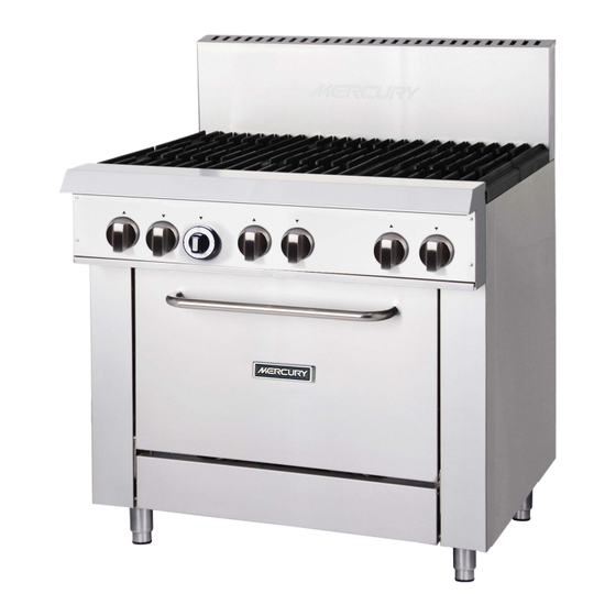
Mercury Gas Oven
Model: M24S-4F M36S-6F
Installation and Operation Instructions
NOTICE: This manual contains important safety instructions which must be
strictly followed when using this equipment.
CAUTION: These models are designed, built, and sold for commercial use only. If
these models are positioned so the general public can use the equipment, make
sure that cautions, warnings, and operating instructions are clearly posted near
each unit so that anyone using the equipment will use it correctly and not injure
themselves or harm the equipment.
middleby.com.au
Advertisement
Table of Contents

Related Manuals for Mercury M24S-4F

Summary of Contents for Mercury M24S-4F
- Page 1 Mercury Gas Oven Model: M24S-4F M36S-6F Installation and Operation Instructions NOTICE: This manual contains important safety instructions which must be strictly followed when using this equipment. CAUTION: These models are designed, built, and sold for commercial use only. If these models are positioned so the general public can use the equipment, make...
- Page 2 IMPORTANT FOR FUTURE REFERENCE Please complete this information and retain this manual for the life of the equipment. For Warranty Service and/or parts, this information is required. Model Number Serial Number Date Purchased WARNING: For your safety, do not store or use gasoline or other flammable vapors or liquids in the vicinity of this or any other appliances.
-
Page 3: Table Of Contents
Installation and Operation Instructions Contents Introduction ..................... 4 Specifications ................... 5 General Pack Contents Gas Supply Requirements Dimensions ....................6 Installation ....................7 Installation Requirements Unpacking Location Clearances Assembly Gas Connection Low Flame Setting Commissioning Operation ....................13 Operation Guide Description of Controls Lighting the Pilot Burner Lighting the Main Burner Cleaning and Maintenance ................. -
Page 4: Introduction
Installation and Operation Instructions Introduction We are confident that you will be delighted with your Mercury Gas Oven, and it will become a most valued appliance in your commercial kitchen. To ensure you receive the utmost benefit from your new Gas Oven, there are two important things you can do. -
Page 5: Specifications
Installation and Operation Instructions Specifications General Commercial heavy duty oven. Pack Contents The following is included: Mercury Gas Oven 2pcs racks 4pcs Feet Instruction Manual Gas Supply Requirements Natural Gas Propane M36S-4F- M36S-4F- M24S-4F M36S-6F M24S-4F M36S-6F Single burner Heat Input 32.5 MJ... -
Page 6: Dimensions
Installation and Operation Instructions Dimensions Dimensions for Freestanding Oven Model Number Exterior Dimensions (Millimeters) M24S-4F 1175 M36S-6F 1175... -
Page 7: Installation
Installation and Operation Instructions Installation Installation Requirements NOTE: • It is most important that this appliance is installed correctly and that operation is correct before use. Installation shall comply with local gas, health and safety requirements. • This appliance shall be installed with sufficient ventilation to prevent the occurrence of unacceptable concentrations of substances harmful to health. - Page 8 Installation and Operation Instructions Installation (Continued) 1. Remove screws and disassemble the top and side wood packaging. 2. Remove plastic wrap and set aside the flue box. 3. Remove the Gas Oven from the pallet for installation. Step 2a: Install the Legs A set of four legs is packed with units ordered with legs.
- Page 9 Installation and Operation Instructions Installation (Continued) Step 2b: Install Casters (options) A set of four casters is packed with units ordered with casters (instead of legs). A threaded leg pad is fastened to the base frame at each corner. Each caster gas a corresponding mating thread.
-
Page 10: Location
Installation and Operation Instructions Installation (Continued) Step 3: Attach Flue Riser Place the flue riser assembly on the range as shown on the appropriate diagram below. Slide the flue riser assembly over the bayonets until it bottom out, as shown below. Secure ends of flue riser assembly with two M6 hex head bolts, flat washers and lock-washers Single-Oven Models Location... -
Page 11: Gas Connection
Installation and Operation Instructions Installation (Continued) Gas Connection NOTE: ALL GAS FITTING MUST ONLY BE CARRIED OUT BY A QUALIFIED PERSON. The Gas Ovens do not require an electrical connection, as they function totally on the gas supply only. It is essential that the gas supply is correct for the appliance to be installed and that adequate supply pressure and volume are available. -
Page 12: Commissioning
Installation and Operation Instructions Commissioning Before leaving the new installation; a. Check the following functions in accordance with the operating instructions specified in the ‘Operation’ section of this manual. • Light the Pilot Burner. • Light the Main Burner. • Turning 'Off' the Main Burner/Pilot. b. -
Page 13: Operation
Installation and Operation Instructions Operation Operation Guide CAUTION: • THIS APPLIANCE IS FOR PROFESSIONAL USE AND IS ONLY TO BE USED BY QUALIFIED PEOPLE. • ONLY QUALIFIED SERVICE PERSONS ARE TO CARRY OUT INSTALLATION, SERVICING OR GAS CONVERSION OPERATIONS. • COMPONENTS HAVING ADJUSTMENTS PROTECTED (E.G. - Page 14 Installation and Operation Instructions Operation WARNING: SURFACE TEMPERATURE OF THE GRIDDLE CAN REACH OVER 300° C WHEN THE APPLIANCE IS OPERATED AT FULL SETTING. 1. Lighting the Top Burners The burners are fitted with individual standing pilots which allows the main burners to be turned ON- OFF without the need to manually re-light the burner each time that it is turned ON, as the burner will be automatically lit itself by the pilot burner.
- Page 15 Installation and Operation Instructions Operation (Continued) Main burner air supply: For efficient burner operation, a proper balance of gas volume and primary air supply must be maintained which will result in complete combustion. Insufficient air supply results in a yellow streaming flame. Primary air supply is controlled by an air shutter on the front of the burner.
-
Page 16: Cleaning And Maintenance
Installation and Operation Instructions Cleaning and Maintenance INITIAL CLEANING: Prior to operating your new oven, thoroughly wash the exterior with a mild detergent or soap solution. Do not use abrasive cleaners, since this might damage the cabinet finish. If the stainless steel surfaces become discolored, scrub by rubbing only in the direction of the finished grain. - Page 17 Installation and Operation Instructions Cleaning and Maintenance (Continued) Do not waste gas and abuse equipment by leaving all burners “FULL ON”, if not required. During idling periods, adjust burner valves to keep top warm. Re-adjust burner valves as required for periods of heavy loads.
-
Page 18: Adjustments
Installation and Operation Instructions Adjustments Warning: Adjustments and service work may only be performed by a qualified technician who is experienced in, and knowledgeable with, the operation of commercial cooking equipment. However, to assure your confidence, contact your authorized service agency for reliable service, dependable advice and other assistance, and of genuine factory parts. - Page 19 Installation and Operation Instructions Adjustments (Continued) CONVERTING FROM LPG TO NG AND VICE-VERSA Turn-off the pilot. Shut-off the main isolation valve and follow the lock-out/tag-out procedure. Remove the gas regulator. Remove the converter cover from the regulator. Use a 22mm spanner. Pull-out the converter and position it to your desired gas type.
-
Page 20: Trouble Shooting
Installation and Operation Instructions Trouble shooting This section provides an easy reference guide to the more common problems that may occur during the operation of your equipment. The fault finding guide in this section is intended to help you correct, or at least accurately diagnose problems with your equipment. - Page 21 Installation and Operation Instructions Troubleshooting RANGE TOP BURNER TROUBLESHOOTING NOTE: Griddle Tops Common checks of all top configurations. Check that the burners are set level in the NOTE: Griddles and Hot Tops must be raised support brackets. and secured or removed. Check that the burners are clean and all ports CAUTION! Before raising or removing are clear.
- Page 22 Installation and Operation Instructions Troubleshooting (Continued) Continued from Previous Page Install the grates or griddle/hot tops. With the gas supply shut off to the range install a pressure tap on the manifold in the Plugged tap provided Install the thermostat bulbs into griddle tops. Install a manometer on the pressure tap.
- Page 23 Installation and Operation Instructions Troubleshooting (Continued) OVEN PILOT DOES NOT WORK Continued to hold the button for 30 seconds. The pilot should light and remain lit after the button is released. Press and hold the button on the oven safety valve and put flame to the pilot.
- Page 24 Installation and Operation Instructions Troubleshooting (Continued) THERMOSTAT GRIDDLE TROUBLESHOOTING If the flame is not correct remove the knobs and bezel.. Remove the knobs and control panel. There is a slotted screw below the stem on the thermostat valve. CAUTION! WIRING BEHIND PANEL.
- Page 25 Installation and Operation Instructions Troubleshooting (Continued) Continued from Previous Page Repeat this procedure at each burner until the temperature stabilizes to within 30℃ of the set Place digital surface temperature temperature instrument in the center of the griddle. If the temperature cannot be set to within 30℃ Allow reading to stabilize to 150℃...
-
Page 26: Replacement Parts List
Installation and Operation Instructions Replacement Parts IMPORTANT: Only genuine authorized replacement parts should be used for the servicing and repair of this appliance. The instructions supplied with the parts should be followed when replacing components. For further information and servicing instructions, contact your nearest authorized service branch. When ordering replacement parts, please quote the part number and the description listing below. -
Page 27: Explosion Drawing
Installation and Operation Instructions Explosion drawing... -
Page 28: Spare Parts List
Installation and Operation Instructions Spare Parts List DESCRIPTION MODEL CODE M24S-4F 20713.6122 M24S-00-24F 20713.6122 M36S-6F 20713.6114 Door Assembly M36S-4F-12F 20713.6114 M36S-2F-24F 20713.6114 M36S-00-36F 20713.6114 M24S-4F 10203.6022 M24S-00-24F 10203.6022 M36S-6F 10203.6022 L-Connector M36S-4F-12F 10203.6022 M36S-2F-24F 10203.6022 M36S-00-36F 10203.6022 10208.6059(oven) M24S-4F M24S-00-24F 10208.6059 (oven) - Page 29 Installation and Operation Instructions Spare Parts List M24S-4F M36S-6F 20713.6130 U Burner M24S-00-24F M36S-4F-12F 20713.6130 Assembly(OVEN) 20713.6130 M36S-00-36F M36S-2F-24F M36S-4F-12F 20802.6001 M24S-00-24F 20802.6001 U Burner Assembly(Griddle) M36S-2F-24F 20802.6001 M36S-00-36F 20802.6001 M24S-4F 20713.6110 M36S-6F 20713.6110 M36S-4F-12F 20713.6110 Door Hinge Assembly M24S-00-24F 20713.6110...
- Page 30 Installation and Operation Instructions Spare Parts List M24S-4F 10208.6021 M36S-6F 10208.6021 M36S-4F-12F 10208.6021 Safety Valve M24S-00-24F 10208.6021 M36S-2F-24F 10208.6021 M36S-00-36F 10208.6021 M36S-4F-12F 22201.6161 M24S-00-24F 22201.6161 Main Pipe Assembly - Right M36S-2F-24F 22201.6161 M36S-00-36F 22201.6161 M24S-4F 20713.6030 M36S-6F 20713.6024 Tray M36S-4F-12F 20713.6030...
- Page 31 Installation and Operation Instructions Spare Parts List M24S-4F 10108.6002 Flame Device System - Front M36S-6F 10108.6002 ODS Injector-0.2 M36S-4F-12F 10208.6025 ODS Injector-0.4 M36S-2F-24F 10208.6026 M24S-4F 20708.6316 Pilot Pipe Front M36S-6F 20708.6316 Assembly M36S-4F-12F 20708.6316 M36S-2F-24F 20708.6316 M24S-4F 20708.6315 Main Pipe Front M36S-6F 20708.6315...
- Page 32 Under warranty period of the appliance, All the part must be replaced by authorized service provider which approved by Middleby, If not, the warranty may be void. NOTICE Any parts that aren’t made by MERCURY may void warranty. NOTICE Middleby and manufacturer of Middleby keep the right to modify the product.
Need help?
Do you have a question about the M24S-4F and is the answer not in the manual?
Questions and answers