Table of Contents
Advertisement
Quick Links
Advertisement
Table of Contents

Summary of Contents for PowerBox CORE
- Page 1 Instruction Manual...
-
Page 2: Table Of Contents
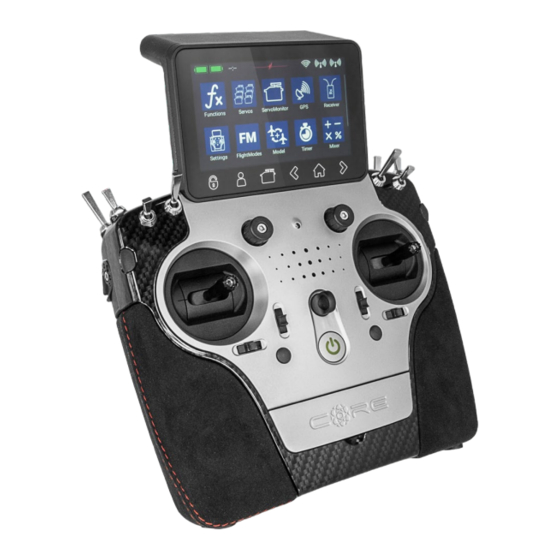
CORE has great presence and allure, which you cannot fail to appreciate when you pick up the transmitter for the first time. The CORE fits perfectly in your hands, and is the perfect tool for controlling your valuable models with precision. -
Page 3: Connections, Controlls
Light sensor 8 Toggle switches Quick-select buttons Optional stick switch Loudspeaker 4 pro- portional controls 4 digital trims On / Off switch 4 push-buttons Quick-select buttons Screen User- Servo History Home screen History unlock defined monitor back forward menu www.powerbox-systems.com... -
Page 4: Initial Steps
Switching on The CORE is switched on by holding the -button pressed in until it lights up red. Release the button briefly, then confirm the power-on process by briefly pressing the button a second time. The transmitter is switched off in exactly the same way. - Page 5 - Create or erase functions Servo monitor Model - Model overview - Load, copy or erase models Flight modes Receiver - Receiver overview - Bind or remove receiver - Range check Virtual switches Speech output File manager Settings - System - Screen www.powerbox-systems.com...
- Page 6 Please be sure to set the date and time of day. A later update will activate the internal GPS of the CORE, and at that time the clock will set itself automatically. It is also important to set your preferred units of measurement: the system sends your choice of Metric or Imperial to the telemetry sensors, and the sensors then deliver all telemetry values using your preferred units, such as kilometres / miles or litres / gallons.
- Page 7 USB memory stick. Note: don’t erase the Demo model! The CORE cannot start if you erase all models from its memory! To create a new model, briefly touch the + button at the bottom of the screen.
- Page 8 If you decide to assign the wing flaps at this point, you will learn to appreciate one of the truly unique features of the CORE. As with the ailerons, you again assign a transmitter control to the flaps. If each flap is operated by a separate servo, you won’t notice anything unusual: you simply assign the flaps to your preferred servo outputs.
-
Page 9: Function Menu
Alternative trim modes are Left and Right; typically these are inten- ded for idle adjustment in the case of engines and turbines. In the Center trim mode any adjustment only affects the center range, i.e. the end-points re- main unchanged. www.powerbox-systems.com... - Page 10 At this point you can select a transmitter control which is used to switch an Expo characteristic, or set it to linear. You can choose any transmitter control from the primary sticks, proportional controls or switches. PowerBox-Systems − World Leaders in RC Power Supply Systems...
- Page 11 At the same time you can observe the effect of any change directly on the servo. www.powerbox-systems.com...
- Page 12 The Center button is used to set a center offset which affects the whole of the servo’s travel. You will see the effect of the change immediately in the graph on the left-hand side. - Curve Editor Press Edit. when you wish to adjust servo travel using a maximum of 17 points. PowerBox-Systems − World Leaders in RC Power Supply Systems...
- Page 13 Note: if you wish, you can reset the servo curve once you return to the Servo Overview. If you accidentally find yourself at the Reset button, that is not a problem: simply select the Curve Editor again, and the curve will still be present there with the settings you last selected. www.powerbox-systems.com...
-
Page 14: Binding A Receiver
You can only re-start the process if you first disconnect the power supply. 2. Press the Bind button on your CORE, then connect the receiver to a power supply. The LED switches to conti- nuous green once the receiver is bound. -
Page 15: Mixer
Selecting Core / M-Link If your transmitter is equipped with a supplemen- tary Multiplex M-Link aerial, you will find the button for switching from the CORE system to the M-Link system right at the top. The M-Link system offers two binding modes:... -
Page 16: Virtual Switches
Select the Virtual Switch button in the menu, then press + to set up a new virtual switch: PowerBox-Systems − World Leaders in RC Power Supply Systems... - Page 17 If you wish to use a switch, you can very easily set the desired switch position to ON. If you select a 3-position switch it is also possible to set two ON positions. Press OK once you have completed your settings. www.powerbox-systems.com...
-
Page 18: Servo Cut-Off
You can now select a switch or linear control as transmitter control by operating it. Yet another option is to use the output of a previously defined logical switch in turn as a transmitter control input. Press OK when you have made your selection. PowerBox-Systems − World Leaders in RC Power Supply Systems... - Page 19 As soon as the transmitter control is moved to the ON position, the servo moves to the previously defined position; you can read off the current value at far right. www.powerbox-systems.com...
-
Page 20: Flight Modes
8. FLIGHT MODES Flight modes, also known as flight phases, are one of the CORE’s most powerful features, but they are still easy to use! You can imagine a flight mode as a copy of a particular model memory, but one with slightly altered settings. - Page 21 Flight Mode tree which indica- te which flight mode is currently active. You can now select various settings for the different flight modes in the Transmitter Control, Trim and Mixer menus after selecting the Single setting at Flight Mode. www.powerbox-systems.com...
-
Page 22: Speech Output
TTS system available; the licence is a chargeable item which is included in the CORE as standard. For each language several male and female voices are available. Due to the file size these are gradually loaded into the transmitter by means of updates. As of Version 1.60 one male and one female voice are available for each language. -
Page 23: Vario
This enables you, for example, to have English expressions spoken using an English voice, even though the CORE is set to German. 10. VARIO The CORE vario offers a number of options for fine-tuning the sound output relating to your model’s climb and sink. a) Sensor The vario must be connected to a bound receiver, and must be visible in the Sensor List;... -
Page 24: File Manager
11. FILE MANAGER The File Manager enables you to exchange files on the SD card in the CORE transmitter with files stored on a USB memory stick. File types include model data, log files and also audio files for audible signals. - Page 25 Technical information: the PowerBox CORE telemetry system and the P²BUS are designed in such a way that each sensor supplies its own information, including sensor name, unit, number of sensor values, decimal point, priority and other data.
- Page 26 Press + in order to select one or more telemetry values for this sensor; the sensor now appears in the list. In the example on the right this is the PBS-V60: PowerBox-Systems − World Leaders in RC Power Supply Systems...
- Page 27 A long press on the sensor name now displays the current address. This is purely for information pur- poses - address management is carried out auto- matically by the CORE. Press the X->Y button in order to change the ad- dress. Another long press on the sensor name will...
- Page 28 Timer The CORE allows you to set up eight separate, inde- pendent timers. If you select the Timer widget type, you will see the screen shown below, where you can adjust the timer settings and set alarms, and add further timers by pressing the + button.
- Page 29 Widgets for individual servo outputs, quick-select for menu entries and also simple notes can be created in the same way as telemetry values. The procedure is the same as for telemetry or timer widgets: keep your finger on a free space on the main screen display, and make your selection as you wish. www.powerbox-systems.com...
-
Page 30: Update
Insert a USB stick in your PC, and follow the on-screen instructions. The USB stick will now be formatted, and all the essential data copied onto it. Once that is finished, switch your CORE transmitter on and wait until it has booted up. -
Page 31: Wifi
14. WIFI If you wish to use the Online Update function you must first set up your WiFi connection. The CORE transmitter can be bound to your stationary router at home, or to a hotspot which you create with your mobile phone. This... -
Page 32: Charging The Transmitter
15. CHARGING THE TRANSMITTER If you wish to charge the CORE, the first step is to open the front cover. Locate the two plugs attached to the mains PSU, and insert either one into the charge socket. If the battery symbol is displayed large and flashing on the screen, this means that you have a reserve for about 20 –... -
Page 33: Mechanical Transmitter Adjustments
The first step is to remove the handrests. Lay the CORE on a soft surface – ideally a thick layer of foam. Now undo and remove all ten socket-head screws holding the back cover. Don’t remove the back cover yet, as the cables for the switches and proportional controls in the cover must first be disconnected. - Page 34 Adjusting the throttle travel The travel of the throttle stick on the CORE is adjustable. This is useful for 3D pilots in particular, as it enables them to set a mechanical limit on throttle travel. Adjustment is carried out by tightening screws 5. The throttle travel can also be set up asymmetrically.
-
Page 35: Calibrating The Transmitter Controls
18. CALIBRATING THE TRANSMITTER CONTROLS Naturally the PowerBox CORE is supplied with all functions correctly calibrated. However, if you wish to swap a switch or replace a broken switch, we re- commend that you re-calibrate the new switch. Re-ca- libration is also necessary if, for example, you limit the throttle stick travel, or change the transmitter mode mechanically. -
Page 36: Core Accessories
The unit features a P²BUS interface for servo and telemetry data, and an auxiliary output which can be con- figured either as SRXL bus or S-BUS. This unit is designed to be connected to our PowerBox power supply systems or a flybarless system. PBR-8E Order No. - Page 37 PBS-P16 Order No. 6622 The PBS-P16 is an ultra-precise pressure sensor for up to 16 Bar. It is designed to work with the PowerBox CORE, but is also suitable for use with other telemetry systems. PBS-T250 Order No. 6621 The PBS-T250 is a five-way temperature sensor for mea- suring cylinder head temperatures.
-
Page 38: Service Note
They are guaranteed “Made in Germany”! That is why we are able to guarantee the PowerBox CORE for a period of 24 months from the initial date of purchase. The guarantee covers proven material faults, which will be corrected by us at no charge to you. As a precautionary measure, we are obliged to point out that we reserve the right to replace the unit if we deem the repair to be economically unviable. -
Page 39: Rf Exposure Statement (Portable Devices)
This device complies with the RF exposure requirements for portable devices. The device is intended for hand- held use, with the transmitter antennas kept more than 60mm from the hands and more than 20cm from the body in normal use. We wish you every success with your new PowerBox CORE! Donauwoerth, September2020 www.powerbox-systems.com... - Page 40 09/2020 PowerBox-Systems GmbH zertifiziert nach DIN EN ISO 9001 Ludwig-Auer-Straße 5 D-86609 Donauwörth Germany +49-906-99 99 9-200 +49-906-99 99 9-209 www.powerbox-systems.com...
Need help?
Do you have a question about the CORE and is the answer not in the manual?
Questions and answers