Table of Contents
Advertisement
Quick Links
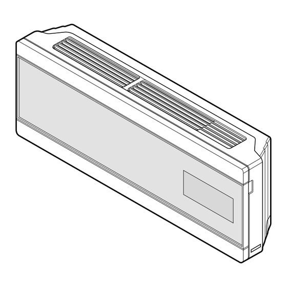
Heat Pump Indoor Unit
INSTALLATION MANUAL
MODELS: LRNN, LRNV-SU/S3 Series
Type: Artcool Deluxe
System
IMPORTANT
• Please read this installation manual completely before
installing the product.
• Installation work must be performed in accordance with
the national wiring standards by authorized personnel
only.
• Please retain this installation manual for future reference
after reading it thoroughly.
LG
Advertisement
Table of Contents

Related Manuals for LG MULTI V LRNV-SU Series


Summary of Contents for LG MULTI V LRNV-SU Series
- Page 1 System Heat Pump Indoor Unit INSTALLATION MANUAL MODELS: LRNN, LRNV-SU/S3 Series Type: Artcool Deluxe IMPORTANT • Please read this installation manual completely before installing the product. • Installation work must be performed in accordance with the national wiring standards by authorized personnel only.
-
Page 2: Table Of Contents
Artcool Deluxe Type Indoor Unit Installation Manual TABLE OF CONTENTS Installation Requirements Required Parts Required Tools Installation Parts ....3 Safety Precautions ....4 Installation Installation guide map Level gauge Four type "A" screws & plastic Screw driver anchors Electric drill Selection of the best location Connecting cable Hole core drill ..........7... -
Page 3: Installation Parts
Installation Parts Installation Parts Installation Plate Installation plate Type "A" screws and plastic anchors Type "B" screws Holder Remote Controller Installation Manual 3... -
Page 4: Safety Precautions
Safety Precautions Safety Precautions To prevent injury to the user or other people and property damage, the following instructions must be followed. Be sure to read before installing the air conditioner. Be sure to observe the cautions specified here as they include important items related to safety. Incorrect operation due to ignoring instruction will cause harm or damage. - Page 5 Safety Precautions Do not modify or extend the Do not let the air conditioner Be cautious when unpacking power cable. run for a long time when the and installing the product. humidity is very high and a door or a window is left open. •...
- Page 6 Safety Precautions Installation Always check for gas (refriger- Install the drain hose to ensure Keep level even when installing ant) leakage after installation or that water is drained away prop- the product. repair of product. erly. • Low refrigerant levels may cause •...
-
Page 7: Installation
Installation Installation Read completely, then follow step by step. Selection of the best location There should not be any heat source or steam • near the unit. More than 5 cm • There should not be any obstacles to prevent the More than 10 cm air circulation. -
Page 8: Piping Method
Installation Piping Method Preparing the indoor unit's piping and drain hose for 3. Tape the tubing, drain hose and the connecting cable. Be sure that the drain hose is located at the installation through the wall. lowest side of the bundle. Locating at the upper Remove the plastic tubing retainer(see illustration side can cause drain pan to overflow inside the below) and pull the tubing and drain hose away from... - Page 9 Installation Tighten the flare nut with a wrench. Wrap the area which accommodates the rear pip- ing housing section with vinyl tape. Spanner (fixed) Indoor Connection unit pipe pipe Flare nut Wrap with vinyl tape Vinyl tape Connection (wide) Torque pipe wrench Connecting cable...
- Page 10 Installation 3. Insert the connecting cable into the indoor unit. Pipe Size[Torque] Don't connect the cable to the indoor unit. Model LIQUID Make a small loop with the cable for easy connec- Ø12.7[5.5kg . m] Ø6.35[1.8kg . m] tion later. Ø15.88[6.6kg .
- Page 11 Installation Bundle the piping and drain hose together by wrapping them with cloth tape over the range CAUTION within which they fit into the rear piping housing section. Installation Information (For left piping) • Good case Pipe For left piping. Follow the instruction below. Drain hose Vinyl tape Press on the upper side of clamp.
-
Page 12: Drain Piping
Installation Drain Piping CAUTION 1. To remove the front panel from the indoor unit, • Bad case remove the front panel from the indoor unit Following bending type from right to left could cause cabinet. problem of pipe damage. Set the air direction louvers up-and-down to the position(horizontally) by hand. -
Page 13: Wiring Connection
Installation Wiring Connection Connect the wires to the terminals on the control board individually according to the outdoor unit connection. • Ensure that the color of the wires of outdoor unit and the terminal No. are the same as those of indoor unit respectively. -
Page 14: Installation Of Remote Controller
Installation Installation of Remote Controller HOW TO MOUNT ONTO A WALL HOW TO INSERT BATTERIES 1. Remove the battery cover from the remote controller. • Do not use rechargeable batteries, • Slide the cover according to the arrow direction. such batteries differ from standard dry cells in shape, dimensions, and per- 2. - Page 15 P/No.: 3828A23004H Printed in Korea After reading this manual, keep it in a place easily accessible to the user for future reference.
Need help?
Do you have a question about the MULTI V LRNV-SU Series and is the answer not in the manual?
Questions and answers