Table of Contents

Summary of Contents for Solid Technologies ALLIANCE HROU 4000
- Page 1 ALLIANCE HROU_4000 User Manual Document Reference: Version: V1.0 Document Status: Release 1 Issue Date: August 26, 2022 Author: Yong Hee Kim Department: R&D Division Team 2 Authorizing Manager: Hyun Seok Chae Confidential & Proprietary 1/28...
- Page 2 REVISION HISTORY No. of Version Issue Date Initials Details of Revision Changes Pages V 1.0 Aug. 26, 2022 Original Technical Support SOLiD serial numbers must be available to authorize technical support and/or to establish a return authorization for defective units. The serial numbers are located on the back of the unit, as well as on the box in which they were delivered.
-
Page 3: Table Of Contents
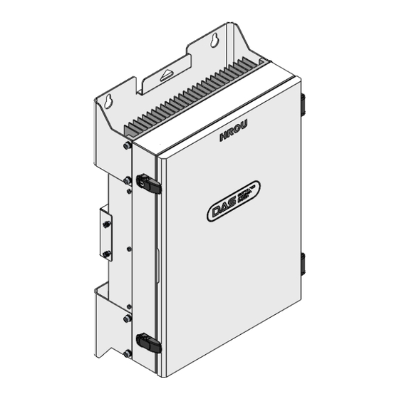
Contents Section1 Safety & Certification Notice ..............5 Section2 System Configuration and Functions ........... 8 2.1 High power 5G Remote ..................8 2.1.1 Specifications of HROU ................9 Block Diagram of HROU_4000 ..............10 2.1.2 2.1.2.1 HROU_4000 block diagram ................ 10 2.1.2.2 HROU_4000 inner look ................ - Page 4 Contents of Figure Figure 1. HROU_4000 outer Look ................ 8 Figure 2. HROU_4000 Block diagram ..............10 Figure 3. Inside of Remote Unit ................. 11 Figure 4. HRDU Outer Look ................13 Figure 5. AC-DC RPSU Outer Look ..............14 Figure 6.
-
Page 5: Safety & Certification Notice
Section1 Safety & Certification Notice Safety & Certification Notice “Only qualified personnel should handle the DAS equipment. Any person involved in installation or service of the DAS should understand and follow these safety guidelines.” - Obey all general and regional installation and safety regulations relating to work on high voltage installations, as well as regulations covering the correct use of tools and personal protective equipment. - Page 6 - Allow sufficient fiber length to permit routing without severe bends. - For pluggable equipment, make sure to install the socket outlet near the equipment so that it is easily accessible. - A readily accessible disconnect device shall be incorporated external to the equipment. - The power of this system shall be supplied through wiring installed in a normal building.
- Page 7 - Certification FCC: This equipment complies with the applicable sections of Title 47 CFR Parts 15, 27 Use of unauthorized antennas, cables, and/or coupling devices not conforming with ERP/EIRP and/or indoor‐only restrictions is prohibited. - Home/personal use is prohibited. UL/CUL: This equipment complies with UL and CUL 1950-1 Standard for safety for information ...
-
Page 8: Section2
Section2 System Configuration and Functions System Configuration and Functions 2.1 High power 5G Remote HROU_4000 is a remote unit supporting both SISO and MINO service of C-Band. HROU_4000 receives TX optical signals from ODU and converts them into RF signals. The converted RF signals are amplified through high-power amps in the corresponding HRDU bands combined with UDCU, PAU, and Cavity duplexer, and then radiated to the antenna port. -
Page 9: Specifications Of Hrou
2.1.1 Specifications of HROU Spec. Item Remark HROU_4000 HRDU_Cband 280MHz 3700 - 3980MHz HRDU_Cband_M The nominal bandwidth HRDU_345 100MHz 3450 - 3550MHz HRDU_345_M LPOI : -19dBm Each port Input power HROU : -50dBm 20 / 40 MHz (+43dBm+1dBm) 3700-3980 MHz 60 / 80 / 100MHz (+45dBm+1dBm) 3450-3550 MHz... -
Page 10: Block Diagram Of Hrou_4000
2.1.2 Block Diagram of HROU_4000 2.1.2.1 HROU_4000 block diagram Figure 2. HROU_4000 Block diagram Confidential & Proprietary 10/28... -
Page 11: Hrou_4000 Inner Look
2.1.2.2 HROU_4000 inner look Figure 3. Inside of Remote Unit 2.1.2.3 HROU part list Unit Description Remark High Remote Drive Unit Consists of UDCU and PAU Optional HRDU X4 Filters and amplifies TX signals; Max 4 Filters and amplifies RX signals in low noise amplifier; Remote Power Supply Unit HROU_4000_PSU (AC) Input power: 110 VAC/220VAC (90~264V) - Page 12 Remote Optic Makes RF conversion of TX optical signals; Converts RX RF signals into optical signals; Compensates optical loss; HROPTIC_4000 5dBo optical link between ODU(OM4) and ROU; 10dBo optical link between ODU(OM1) and ROU; Fiber Connector: SC/APC Connector; Optical Wavelength: 1310/1330/1550 WDM; Communicates with BIU/OEU through the FSK modem Remote Central Processor &...
-
Page 13: Function By Unit
2.1.3 Function by unit 2.1.3.1 High Remote Drive Unit (HRDU) When receiving TX signals from each band through Remote Optic, HRDU filters the signals and amplifies them with High Power Amplifier. The unit also filters RX signals given through a cavity filter and amplifies them to send the signals to Remote Optic. -
Page 14: Remote Power Supply Unit (Rpsu)
2.1.3.2 Remote Power Supply Unit (RPSU) There are 2 types of RPSU in the HROU to supply active modules in the enclosure and receive power from the external. They are the DC/DC PSU receiving input -48V and the AC/DC PSU receiving input 110V/220V from external. -
Page 15: Remote Optic (Hroptic_4000)
2.1.3.3 Remote Optic (HROPTIC_4000) Remote Optic converts optical signals into RF signals and performs vice versa. It also has internal ATT for optical compensation to compensate for optical cable loss. It provides two paths in pairs (TX/RX) to transport RF signal to ADD On port. Figure 7. -
Page 16: Multiplexer
Figure 8. HROU_4000_DTU Outer Look 2.1.3.5 Multiplexer A multiplexer is called a Combine Unit (CU) since it works as a module to combine or distribute multiple signals into one or two antennas. This device has a port to combine multiple signals. You need to connect the input and output ports of RDU to the corresponding port of the multiplexer. -
Page 17: Bottom Of Hrou_4000
2.1.4 Bottom of HROU_4000 2.1.4.1 Functions Figure 10. The Bottom Look of HROU_4000 Port Remark SC/APC, Waterproof Optic Port Optic Input port N Type-Female T/RX RF Port Connected to transmit TX to AOR and receive RX signals from ARU. ANT1 DIN-type female_CU SISO port ANT2 DIN-type female_CU MIMO port... -
Page 18: Section3
Section3 System Installation 3.1 HROU_4000 Installation This chapter describes how to install each unit and optical cable, along with the power cabling method. In detail, the chapter describes how to install shelves or enclosures of each unit, the power cabling method, and the optical cabling and RF interface. - Page 19 Figure 11. How to install HROU_4000 Confidential & Proprietary 19/28...
-
Page 20: Hrou_4000 Wall Mount Installation
Figure 12. Dimension used to install HROU_4000 on the WALL 3.1.3 HROU_4000 Wall Mount Installation HROU’s installation bracket is attached to the enclosure when HROU is delivered. Users do not need to remove the bracket to install the enclosure. Simply secure four M12 mounting bolts tightly as the procedures below: Install 2 of the M12 mounting bolts roughly halfway on the enclosure and install the enclosure over the bolts and secure the bolts tightly. -
Page 21: Hrou_4000 Components
Figure 13. Procedures of installation 3.1.4 HROU_4000 components HROU_4000 has the following components: Unit Description Remark Enclosure Including Wall mounting bracket HROU_4000_DTU HROPTIC_OPTIC Common HROU_PSU AC 110/220V or DC -48V Part Interface_B’d Ass’y FAN/External Alarm interface FAN UNIT 2 FANs are inside CU_Cband-345 Optional HRDU_Cband, HRDU_Cband_M,... -
Page 22: Hrou_4000 Power Cabling
The common part of HROU should have an enclosure and it is equipped with HROU_4000_DTU to inquire and control the state of each module, R_OPTIC to make both electronic-optical and optical-electronic conversions, and RPSU to supply power to HROU. HROU should have a power cable for the external rectifier or to supply the required power. -
Page 23: Hrou_4000 Ground Cabling
Figure 14. How to install power cable Assembly sequence Insert the power cable into the CABLE GLAND Assembly as shown ("A"=M4 LUG) As shown in the GrOUND CABLE graphic ("B"=M4 LUG) Tighten CABLE GLAND NUT (Torque = 5.5N·m) 3.1.6 HROU_4000 Ground cabling The Grounding terminal is located at the bottom of the HROU enclosure, fixed by M6 screws. - Page 24 Figure 15. Location of Ground Terminal The specification of the compression terminal is like the image below. Figure 16. Terminal Information The required part number is JOCT 16-6 supporting AWG#6. The way to install the grounding cable complies with the below procedures. Confidential &...
- Page 25 Figure 17. How to install Ground Terminal The procedures are: Loosen two M6 screws and then take the compression terminal off. Insert an AWG#6 grounding wire into the terminal and then compress the terminal using a tool. Assemble the terminal made in step 2 using two M6 screws. Cut the ground wire to a proper length and connect it to the earth’s ground source (A round terminal combined with the 16 mm²(6 AWG)-or-thicker wire is for the permanent grounding.)
-
Page 26: Hrou_4000 Optical Cable
3.1.7 HROU_4000 Optical Cable The Optical Connector is located at the bottom of the remote unit enclosure. An optical cable can be connected to the HROU by using connectors. Figure 18. Location of Optical Connector Figure 19. How to install Optical cable Confidential &... -
Page 27: Mounting Of Hrdu_4000
Assembly sequence 1. Insert the optical cable into the CABLE GLAND 2. Assemble as shown. 3. Tighten the CABLE GLAND NUT (Torque = 5.5N·m) 3.1.8 Mounting of HRDU_4000 HROU_4000 has slots to enable up to four HRDU modules to be mounted in. You can mount an HRDU into the designated slot surely. -
Page 28: Replacing A Fan Unit
Secure 4 screws with a #1 tip-sized crosshead screwdriver to fasten the HRDU. Figure 21.How to mount HRDU 3.1.9 Replacing a FAN Unit Figure 22. How to change fan units The assembly procedure is as follows: Disconnect the cable connector (If the fan unit is dismantled without disconnecting the cable, care must be taken as this may apply a great deal of force to the cable.) Remove the four captive screws of the fan unit.
Need help?
Do you have a question about the ALLIANCE HROU 4000 and is the answer not in the manual?
Questions and answers