
Summary of Contents for Heilig & Schwab Smart-Pro IV
- Page 1 User Manual Smart-Pro IV Heilig & Schwab GmbH & Co. KG Haystraße 24 55566 Bad Sobernheim GERMANY T: +49 (0) 67 51 / 93 12-0 F: +49 (0) 67 51 / 93 12-15 info@heilig-schwab.de www.heilig-schwab.de...
- Page 2 Smart-Pro IV Neither the whole nor any part of this documentation may be reproduced, passed on to third parties, stored in a database system or translated into another language without the written permission of Heilig & Schwab GmbH & Co. KG.
-
Page 3: Table Of Contents
Smart-Pro IV Table of contents 1 GENERAL NOTES _______________________________________________________ 6 1.1 P ____________________________________________________________________ 6 URPOSE 1.2 D ____________________________________________________________ 6 ELIVERY SCHEDULE 2 SAFETY INSTRUCTIONS _________________________________________________ 7 2.1 G ___________________________________________________ 7 ENERAL SAFETY INSTRUCTIONS 3 COMPATIBILITY STATEMENT _____________________________________________ 8 3.1 E... - Page 4 Smart-Pro IV 9.1.1 Measuring with fixed cross hairs _____________________________________________33 9.1.2 Measuring at the centre of the fixed cross hairs _________________________________34 9.1.3 Maximum _______________________________________________________________35 9.1.4 Preset __________________________________________________________________36 9.2 M ____________________________________________________37 EASUREMENT PROCEDURES 9.2.1 Point measurement _______________________________________________________37 9.2.2 Line measurement ________________________________________________________38 9.2.3 Detailed description of measurement procedures ________________________________38 9.3 M...
- Page 5 Smart-Pro IV 11.4 S ___________________________________70 UMMARY MAIN PERFORMANCE CHARACTERISTICS 12 CLEANING ___________________________________________________________ 71 13 GUARANTEE TERMS __________________________________________________ 72 14 LEGAL NOTICE _______________________________________________________ 73 Heilig & Schwab GmbH & Co. KG Page 5...
-
Page 6: General Notes
1 General Notes 1.1 Purpose The Smart-Pro IV with colour screen is an imaging system with touchscreen, integral camera and counter analysis for two axes. Because of its small dimensions it can be fitted directly to the measuring machine’s optical equipment carrier. -
Page 7: Safety Instructions
1. Do not expose the Smart-Pro IV to direct sunlight. 2. Do not expose the Smart-Pro IV to excessive damp and do not pour fluids over the equipment. 3. All maintenance work must only be carried out by authorised customer service personnel. -
Page 8: Compatibility Statement
Unit type: Imaging 3.1 Electromagnetic compatibility (EMC) The Smart-Pro IV meets the conditions of standards EN 61000-6-4 (emission) und EN 61000-6-2 (immunity). These threshold values give sufficient protection against dangerous electromagnetic radiation for the environment. This applies as long as the product has been fitted and used in accordance with the instructions. -
Page 9: Assembly
Aligning the Smart-Pro IV and the light on an optical axis Procedure: 1. Fix the Smart-Pro IV and the light in the measuring unit optical equipment carrier in such a way that, ideally, they face each other on an optical axis. -
Page 10: Operation And Display
Smart-Pro IV 5 Operation and Display 5.1 Operating elements 5.1.1 Gestures The Smart-Pro IV is operated by gesture control via the integrated touch screen. Designation Presentation Description Example Start function Briefly touch surface Choose option with fingertip. Call up screen keyboard ... -
Page 11: Input Window
Smart-Pro IV 5.1.2 Input window Typing or swiping gestures also opens input windows and list windows. The changes made to the Smart Pro IV settings in the input windows are saved when the window is closed. In windows, for example "Options", which because of the limited window size display only a subset of all entries, the window content can be scrolled up and down using vertical drag gestures. -
Page 12: Screen Representation
Smart-Pro IV 5.2 Screen representation Resolution: 800 x 480 pixels The actual Smart-Pro IV screen layout may differ in colour and design from the illustrations given in this handbook as examples because any colour scheme is possible. However, the main layout of the screen interface remains unaffected by this. -
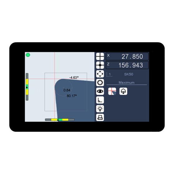
Page 13: Live Image
Smart-Pro IV 5.2.1 Live image The Live image shows the object recorded by the camera, control elements and adjustment aids: Cross hairs Measuring lines (auxiliary lines) Adjustment bars Analysis window Measurement errors displayed as a red or a green button ... - Page 14 The analysis window is shown in the live image as a coloured square. It marks the area where the Smart-Pro IV carries out contour measurements so that the most interesting area can be selected even with objects that have complex contours.
-
Page 15: Favorits Bar
Smart-Pro IV 5.2.2 Favorits bar In the Favorites bar up to seven selected menu icons can be taken over by simply dragging and dropping (Drag and Drop). The favorites are always directly available to the operator and are stored in a non-volatile memory. -
Page 16: Status Area
Measurement results Setup menu 5.2.3.1 Counter value display The Smart-Pro IV analyses two connected measuring systems and displays the counter values determined in the counter value display. The counter value display has the function of a button. Touching the counter value display stops the counter value (Counter stop). - Page 17 Swipe to the left: Increment measure / reset to zero Increment 5.2.3.2 Tool reference display When it is delivered the Smart-Pro IV displays an icon for the tool reference 0. The tool reference display has the function of a button. Touching will list all stored reference points.
- Page 18 Smart-Pro IV 5.2.3.3 Operating mode The current status of the imaging system is displayed. The operating mode display has the function of a button. Touching will restart the operating mode (here for example "Maximum"). Operating mode display 5.2.3.4 Measurement procedures The selected measurement procedure is displayed.
- Page 19 Smart-Pro IV 5.2.3.6 Measurement results display The results of the integral measuring programs, such as line, angle and radius are displayed with additional information on tolerances. Here as an example the result display for an angle measurement. Meas. results display 5.2.3.7 Setup menu...
-
Page 20: Menu
Smart-Pro IV 6 Menu 6.1 Setup menu The setup menu is opened by a horizontal swipe from the right edge of the status area into the status area. Setup Info Imaging Focusing Aligning the camera Lighting Coordinate system... - Page 21 Smart-Pro IV Setup Corrections Linear correction: X Linear correction: Z Parallelism correction Corr. in sections: X Options Corr. in sections: Z View Absolute zero point Password Service Factory settings Delete tool references USB Support Program update...
-
Page 22: Measurement Program Menu
Smart-Pro IV 6.2 Measurement program menu The measurement program selection window is opened by a vertical swipe movement from the bottom of the live image into the live image. Meas. programs Measuring Total image Measure centre Line Maximum Angle... -
Page 23: Shortcut Menu
Smart-Pro IV 6.3 Shortcut menu A shortcut menu is a special object-dependent menu that can be called by a hold gesture on the object. 6.3.1 Live image in maximum mode Shortcut menu for selecting additional functions. Imaging Incident light Evaluation window max. -
Page 24: Live Image In Illumination Mode
Smart-Pro IV 6.3.3 Live image in illumination mode Shortcut menu to select other functions, such as: Imaging Intensity Brightness can only be set automatically if there is nothing in the camera's visual range. 6.3.4 Live image in incident light mode Context menu in incident light mode for switching the lights on and off and adjusting the brightness. -
Page 25: Basic Settings (Hardware Setup)
Optical axis Working distance Aligning the Smart-Pro IV and the light on an optical axis 7.2 Setting the working distance The working distance is defined as the distance between the front edge of the camera lens and the object to be measured, for example a tool cutting edge. This measurement is preset by the design and the production tolerances of the camera lens and must be set when installing the optical components. -
Page 26: Aligning Camera
3. Loosen the camera lens clamping device on the optical equipment carrier and position the Smart-Pro IV in such a way that this position (indicated in colour) deviates as little as possible from the ideal setting. 4. Fasten the camera lens clamping device on the optical equipment carrier and make sure not to modify the working distance when aligning the camera. -
Page 27: Setting Illumination
Smart-Pro IV 7.4 Setting illumination After the camera is aligned, the homogeneity and brightness of the illumination must be checked and set (if necessary). To do this, check the brightness distribution across the camera sensor (top, centre, bottom). Three differently coloured lines must be visible. -
Page 28: Measuring With Imaging
Smart-Pro IV 8 Measuring with imaging In order to achieve exact measurement, the optical components must be aligned precisely. You'll find details on this in the "Basic settings (hardware setup)" chapter. For each measurement procedure ensure that the edges of the object to be measured are not dirty, because this could lead to incorrect measurement results. -
Page 29: Selecting A Tool Reference
Smart-Pro IV 8.1 Selecting a tool reference The system offers you the opportunity to create, save and manage tool references. The 0 (zero) tool reference is fixed and cannot be deleted. It cannot be edited and will therefore not be displayed in the tool... -
Page 30: Starting A Measurement Procedure
Smart-Pro IV 8.2 Starting a measurement procedure When switched on, the system runs in accordance with the settings made during Setup. If a counter module is connected, the system waits for the reference marks of the connected measuring systems to be transferred. -
Page 31: Ending The Measurement Procedure
Smart-Pro IV 8.3 Ending the measurement procedure When the measurement has been completed, the data can be sent to a printer or a 8.3.1 Printing the measurement results The formats (layout) for labels and lists are defined in the output format of the Smart- Pro IV. -
Page 32: Imaging
Smart-Pro IV 9 Imaging To describe the image analysis, we distinguish between: Measuring methods Measurement procedures Measurement programs 9.1 Measuring methods Here there are two main measuring methods: fixed cross hairs flying cross hairs In the case of measurements with fixed cross hairs, all measurements relate to the original cross hair co-ordinates shown. -
Page 33: Measuring With Fixed Cross Hairs
Smart-Pro IV 9.1.1 Measuring with fixed cross hairs Meas. programs Measuring After selection the system analyses the object contour and automatically suggests a measurement procedure for carrying out the measurements immediately. The measurement procedure used is simultaneously displayed in the status window. -
Page 34: Measuring At The Centre Of The Fixed Cross Hairs
Smart-Pro IV 9.1.2 Measuring at the centre of the fixed cross hairs Meas. programs Measure centre With this mode it is possible to position an edge point exactly in the cross hairs’ origin point. This is indicated by the adjustment bar. The edge point is exactly in the cross hairs’... -
Page 35: Maximum
Smart-Pro IV 9.1.3 Maximum Meas. programs Maximum In this case, measurement is carried out using flying cross hairs. After selection the system analyses the object contour and automatically suggests a measurement procedure for carrying out the measurements immediately. The measurement procedure used is simultaneously displayed in the status window. -
Page 36: Preset
Smart-Pro IV 9.1.4 Preset Meas. programs Preset In this case, measurement is carried out using flying cross hairs. After selection the system analyses the object contour and automatically suggests a measurement procedure for carrying out the measurements immediately. The measurement procedure used is simultaneously displayed in the status window. -
Page 37: Measurement Procedures
Smart-Pro IV 9.2 Measurement procedures Two main measurement procedures are used to analyse the contour of an object. Point measurement Line measurement Combining these two procedures further detailed measurement procedures are resulting. When one of the following measurement programs is started, the image processing automatically selects a measurement procedure and displays the corresponding symbol in the measurement procedure display in the status window. -
Page 38: Line Measurement
Smart-Pro IV 9.2.2 Line measurement Line measurement analyses one or more of the object’s straight contour sections and determines the relevant angles. 9.2.2.1 Line measurement using fixed cross hairs Measuring lines which pass through the displayed fixed cross hairs' origin point and run parallel to the determined straight contour sections are drawn and their angles to the crosshairs displayed. - Page 39 Smart-Pro IV Icon Measurement Description procedure L1-PX L2-PX L1-PZ L2-PZ L1-L2 Heilig & Schwab GmbH & Co. KG Page 39...
- Page 40 Smart-Pro IV Icon Measurement Description procedure L1-L2-PX L1-L2-PZ PX-PZ Heilig & Schwab GmbH & Co. KG Page 40...
-
Page 41: Measurement Programs
Smart-Pro IV 9.3 Measurement programs Meas. programs Total image Line Angle Radius Measurement programs perform specific measurement tasks of image processing. The measurement programs offered can be used, regardless of the measurement procedure selected. When setting a user-defined measuring point, the imaging program looks for an edge pixel in the proximity (see „Options>Capture edge“). -
Page 42: Total Image
Smart-Pro IV 9.3.1 Total image The "Total image" function determines the outer contour of a measurement object and thus the effective contour of a rotary tool in the work piece. Symbol picture „Total image“ During the rotation of an object imaged in transmitted light, the outer edge profile is determined and displayed continuously. -
Page 43: Angle
Smart-Pro IV 9.3.3 Angle The "Angle" measurement function is used to visually measure the enclosed angle between two lines. When the user has defined two lines (by defining two or more points per line), the angle is calculated and displayed in the status window together with the x0 and z0 intersection point co-ordinates, for both lines. -
Page 44: Auxiliary Functions
Smart-Pro IV 9.4 Auxiliary functions 9.4.1 Analysis window (Range) The analysis window can be used to limit the contour progression relevant for a measurement. Contour sections outside the analysis window are then not included in the measurement. Procedure: 1. Move the object into the camera’s visual range. -
Page 45: Configuration (Software Setup)
Firmware version Hardware number Serial number (number of device) Your Smart-Pro IV can be clearly identified by the hardware number or the serial number. Please call these numbers for service requests. Heilig & Schwab GmbH & Co. KG... -
Page 46: Imaging
Smart-Pro IV 10.2 Imaging 10.2.1 Align the camera Setup Imaging Align the camera „Basic settings / Align camera“. See chapter 10.2.2 Illumination Setup Imaging Lighting „Basic settings / Setting illumination“. See chapter 10.2.3 Coordinate system Setup ... -
Page 47: With Measure Centre
Smart-Pro IV 10.2.5 With Measure centre Setup Imaging With Measure centre Using "With Measure centre" you can approach and select the necessary measurement points with the original cross hairs. This is an alternative option to the line, angle and radius measurement functions. -
Page 48: Printer (Output Format)
Smart-Pro IV 10.3 Printer (Output format) The printer formats for labels and lists are defined in the output format. Setup Output format For labels, the required format can also be selected from a format template catalogue. 10.3.1 Format template catalogue... -
Page 49: Counter
Smart-Pro IV 10.4 Counter Setup Counter Axis 1 Axis 2 These system settings can be protected by a password. This operating mode enables you to modify the axis names shown on the counter value displays and to configure the measurement system inputs separately. -
Page 50: Corrections
Smart-Pro IV 10.5 Corrections 10.5.1 Linear corrections Setup Corrections Linear correction: X Linear correction: Z These system settings can be protected by a password. In these operating modes, you can correct linearity errors on individual axes. Using an end measurement (= nominal dimension), a ∆ value is determined by comparing actual and set point values - the system then creates a linear correction function based on the ∆... -
Page 51: Parallelism Correction
Smart-Pro IV 10.5.2 Parallelism correction Setup Corrections Parallelism correction This system setting can be protected by a password. In this operating mode, you can correct errors involving parallelism and rectangularity to an object's rotation axis (tool centre). Depending on the measured Z values, X values are corrected in such a way that the tool centre runs parallel to the Z axis - and depending on the measured X values, Z values are corrected in such a way that the X axis runs at a 90°... -
Page 52: Correction In Sections
Smart-Pro IV 10.5.3 Correction in sections Setup Corrections Corr. in sections: X Corr. in sections: Z This system settings can be protected by a password. With this function, linearity errors of the relevant measuring axis can be corrected section by section. -
Page 53: Options
Smart-Pro IV 10.6 Options Setup Options This system settings can be protected by a password. This operating mode gives you the option of setting specific system settings so that they are automatically selected even after the system is restarted. -
Page 54: View
Smart-Pro IV 10.7 View Setup View These system settings can be protected by a password. This operating mode gives you the option of setting specific live image settings so that they are automatically selected even after the system is restarted. -
Page 55: Angle Ranges
Smart-Pro IV 10.7.1 Angle ranges Case Sketch Description Angle reference axis: horizontal 0° ... 360° 0°/ Anticlockwise + 360° -180° ... +180° ±180° 0° Anticlockwise + ±90° -90° ... +90° 0° 0° Anticlockwise + ±90° ±45° 0° ±45° -45° ... +45°... - Page 56 Smart-Pro IV Case Sketch Description Angle reference axis: vertical 0° / 360° 0° ... 360° Clockwise + 0° -180° ... +180° Clockwise + ±180° 0° -90° ... +90° ±90° ±90° Clockwise + 0° ±45° 0° ±45° -45° ... +45° 0°...
-
Page 57: Password
Smart-Pro IV 10.8 Password Setup Password This system setting can be protected by a password. Important system settings can be protected from unauthorised access by allocating a password. The following options are available for entering a password: none It is not necessary to enter a password when selecting a protected operating mode (factory setting). -
Page 58: Service
Smart-Pro IV 10.9 Service 10.9.1 Factory settings Setup Service Factory settings It may be necessary to load the factory settings (default values) to maintain the system. This menu item can be protected by a password. Saved tool references will be deleted! 10.9.2 Delete tool references... -
Page 59: Usb Support
10.9.3.3 Loading a configuration Setup Service USB Support Load configuration The configuration (setting parameters of the setup) of a Smart-Pro IV that has been saved in advance can be loaded. 10.9.3.4 Saving a configuration Setup Service... - Page 60 Smart-Pro IV 10.9.3.5 Loading tool references Setup Service USB Support Load tool references Reference points saved in advance can be loaded. 10.9.3.6 Saving tool references Setup Service USB Support Save tool references Reference points can be stored for backup or for transferring the data to another device.
-
Page 61: Technical Data
11.1.1 Connector layout 12 V DC Transmissive light Smart-Pro IV connections (bottom of the unit) *1) USB port for printer, USB Counter 026, mouse, keyboard, external storage medium over an USB hub Heilig & Schwab GmbH & Co. KG... -
Page 62: Power Supply 12 V Dc
Smart-Pro IV 11.1.2 Power supply 12 V DC The unit is supplied with power using a DC socket. Power supply 12 V DC The negative terminal of the power supply may be earthed. Tolerance ± 5 % Power consumption < 24 W, typical 7 W A corresponding 100 –... -
Page 63: Usb Port
Smart-Pro IV 11.1.4 USB port Version: USB 1.1 Design: Socket, type A Function: Host Transfer rate: 12 Mbps / Full Speed and 1.5 Mbps / Low Speed Length of cable: maximum 5 metres (max. 25 metres with USB repeater cable) The USB repeater cable is an active unit for extending a USB connection. - Page 64 Smart-Pro IV 11.1.4.2 Counter inputs (USB Counter 026) The two scales are each connected by an USB Counter 026 to the Smart-Pro IV. The signal input can be used either as voltage input or TTL input. TTL input Signal...
- Page 65 Smart-Pro IV 11.1.4.3 Mouse HID-compatible USB mouse devices are supported. (HID = Human Interface Device) 11.1.4.4 Keyboard HID-compatible USB keyboards are supported. 11.1.4.5 External storage medium External storage media (e.g. USB stick) with FAT32 file systems are supported. Heilig & Schwab GmbH & Co. KG...
-
Page 66: Mechanical And Physical Specifications
Smart-Pro IV 11.1.5 Mechanical and physical specifications 11.1.5.1 Smart-Pro IV with 5.7" display Notes Housing * Two-piece metal housing: Rear wall as support plate for sensor board and universal ring with lens. Display housing with display frame Material... - Page 67 Smart-Pro IV 11.1.5.3 Reproducibility Information about object analysis reproducibility can only be given if the optical components are aligned precisely. Precise reproducibility data must be determined based on each complete system (imaging and machine). Notes Lengths approx. ± 2 µm...
-
Page 68: Camera
Smart-Pro IV 11.2 Camera The camera is integrated in the Smart-Pro IV's housing. Notes 1/3" – CMOS SW sensor, Sensor 0.3 megapixels Resolution 640 x 480 pixels Interface digital 11.2.1 Lenses Notes Type of lens telecentric View area approx. 6.5 x 6.5... -
Page 69: Transmissive Light
Smart-Pro IV 11.3 Transmissive light 11.3.1 Transmissive light HS-DL5 with VPL532 lens Notes Image HS-DL5 transmissive light Type of illumination telecentric with special LED Colour of the light white Operating current 0 - 12 mA Power consumption < 0.1 W 60 –... -
Page 70: Summary / Main Performance Characteristics
Smart-Pro IV 11.4 Summary / main performance characteristics 7“ capacitive LCD touch display Display Display resolution 800 x 480 pixels Operation Capacitive touch Power supply 12 V DC Interface 1 USB, Type A (Host) Counter value displays Yes / 2... -
Page 71: Cleaning
Smart-Pro IV 12 Cleaning To clean the screen, remove the power cable. Use a soft, slightly damp, lint-free cloth. Avoid getting moisture in openings. Don't use window cleaners, household cleaners, aerosol sprays, solvents, ammonia, abrasives, or cleaners containing hydrogen peroxide. -
Page 72: Guarantee Terms
During this guarantee period any faulty products will either be repaired at the manufacturer or replaced. This applies only if the Smart-Pro IV has been operated by appropriately trained personnel. -
Page 73: Legal Notice
Smart-Pro IV 14 Legal notice Editor Heilig & Schwab GmbH & Co. KG Haystraße 24 55566 Bad Sobernheim Germany Heilig & Schwab GmbH & Co. KG Page 73...
Need help?
Do you have a question about the Smart-Pro IV and is the answer not in the manual?
Questions and answers