Table of Contents
Advertisement
Quick Links
FELLER ENGINEERING
GmbH
AT265
2-channel
DMS-amplifier module
with digital display
User Manual
for firmware V1.06
Tel.: +49(6074)8949-0
FELLER ENGINEERING
GmbH
Carl-Zeiss-Straße 14
Fax: +49(6074)8949-49
63322 Rödermark / Germany
Technical-Hotline: +49(6074)8949-31
Internet: www.fellereng.de
eMail: info@fellereng.de
Version 1.06
Issued: 04/2018
Advertisement
Table of Contents

Subscribe to Our Youtube Channel
Summary of Contents for FELLER ENGINEERING AT265
- Page 1 FELLER ENGINEERING GmbH AT265 2-channel DMS-amplifier module with digital display User Manual for firmware V1.06 Tel.: +49(6074)8949-0 FELLER ENGINEERING GmbH Carl-Zeiss-Straße 14 Fax: +49(6074)8949-49 63322 Rödermark / Germany Technical-Hotline: +49(6074)8949-31 Internet: www.fellereng.de eMail: info@fellereng.de Version 1.06 Issued: 04/2018...
-
Page 2: Table Of Contents
AT265 User Manual Content Short description ....................4 Symbols used: Block diagram Quick start 1.3.1 Electrical connection of the module 1.3.2 Adaptation of the module to the used sensor 1.3.3 Calibration of the module under depressurized condition 1.3.4 Adaptation to specific requirements Important instructions ................... - Page 3 FELLER ENGINEERING AT265 User Manual GmbH 8.1.1 Suitable strain gauge measuring bridges Calibration procedure 8.2.1 Starting of the calibration procedure via the digital input 8.2.2 Starting of the calibration procedure via the keyboard 8.2.3 Display of calibration results Appendix .......................30 Definition „Namur NE43“...
-
Page 4: Short Description
(as current and voltage output each), two 24V digital outputs, as well as two potential-free relay contacts available. The function of the AT265 monitors especially two pressure sensors that must be mounted in nearly identical positions to be able to monitor the occurring pressure values in the machine in a redundant way. -
Page 5: Block Diagram
FELLER ENGINEERING AT265 User Manual GmbH 1.2 Block diagram Issued: 04/2018 Page 5... -
Page 6: Quick Start
AT265 User Manual 1.3 Quick start After executing the steps listed below, the module can be put in operation fast and success- fully within a short time: 1.3.1 Electrical connection of the module Connect the two sensors to the terminal X1 and X2 (chapter 5.2.2.1and 5.2.2.2) Connect the current output 4 20mA for the acquisition of the measured data (chapter 5.2.2.4 or... -
Page 7: Important Instructions
FELLER ENGINEERING AT265 User Manual GmbH 2 Important instructions 2.1 General safety instructions This device has been developed for industrial applications and for the installation in a switch cabinet. The electrical connections are to be installed by an electrician! Only authorized specialist personnel are allowed to put the device into oper-... -
Page 8: Putting Out Of Service
AT265 User Manual 3.1 Putting out of service Because the potential-free alarm contacts are open under deenergized conditions and the 24VDC outputs are at 0V, the "alarm" status is reported to the automation level if the device is switched off. -
Page 9: Care And Maintenance
FELLER ENGINEERING AT265 User Manual GmbH 4 Care and maintenance No special measures for maintenance or care are required. Replaceable wearing parts or parts that have to be calibrated mechanically are not included. No intervention in the module is required for calibration of the strain gauge bridges. -
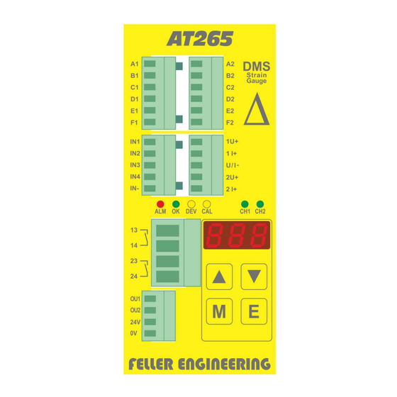
Page 10: Terminal Assignment, Display And Controls
AT265 User Manual 5 Terminal assignment, display and controls The module provides several connection facilities, 6 status LEDs, a 7-degment display and a keyboard with 4 keys. They are arranged on the front of the device as shown in the next figure. -
Page 11: Design Of Connections
FELLER ENGINEERING AT265 User Manual GmbH 5.2 Design of connections 5.2.1 General instructions for polarizing key Each of the connection terminals X1..X6 described here is designed as male connector and coded in a way that it can only be used for one connection in this device. -
Page 12: X4: Analog Outputs
AT265 User Manual 5.2.2.4 X4: Analog outputs X4.1 U+ 1. Voltage output 0..5 VDC or 0..10 VDC X4.1 I+ 1. Current output 0..20 mA or 4..20 mA X4.U/I- Reference potential for all analog outputs An external wiring of this terminals is stringently required. -
Page 13: X6: Power Supply
FELLER ENGINEERING AT265 User Manual GmbH 5.2.2.7 X6: Power supply X6. 24V Power supply 24 VDC (5W; 18VDC – 32 VDC) X6. 0V Power supply, earth (not internally connected with X3:IN- or X4:U/I-) Fuses of 24 VDC power supply shall be installed externally. -
Page 14: Control Buttons
AT265 User Manual 5.5 Control buttons Menu control: Go up by one menu point In input mode: Increment value by 1 Menu control: Go down by one menu point DOWN In input mode: Decrement value by 1 Change over between channel 1 and 2 for the display val- MODE In input mode: Stop entry abortive. -
Page 15: Operation
FELLER ENGINEERING AT265 User Manual GmbH 6 Operation 6.1 Switching on of module After the module has been switched on by applying of the supply voltage, first the module name is shown in the display for some seconds (e.g. ) and then its version number ... -
Page 16: Value Entry
AT265 User Manual 6.4.2 Value entry The arrow keys are used for setting the desired parameter values. As long as the keys re- mains pressed, only one setpoint value will be visible. If the key is released, the parameter name and the value will be displayed in turns. The set value must be confirmed within 3 sec- onds using the E key. -
Page 17: List Of Parameters
FELLER ENGINEERING AT265 User Manual GmbH 6.7 List of parameters Display Meaning Lower limit value, relative to the maximum displayed value Upper limit value 1 relative to the maximum displayed value Upper limit value 2 relative to the maximum displayed value ... -
Page 18: Parameterdescriptions In Detail
AT265 User Manual 6.8 Parameterdescriptions in detail Lower limit value, relative to If one of the two measured values undershoots the here pre-set value, the The smaller LO alarm will be triggered. one of the ... - Page 19 FELLER ENGINEERING AT265 User Manual GmbH Upper limit value 2, relative to If the measured value of the second sensor exceeds the here pre-set value, 1 the HI alarm will be triggered. Default Example: = 350,...
- Page 20 Unit seconds The setting of 0 enables a direct alarm without delay. Function of the 2nd analog output In module AT265, this function is not available Default Unit Smallest permitted negative measured value If the measured value is negative, its absolute value may not exceed the limit value in % that has been pre-set here.
- Page 21 FELLER ENGINEERING AT265 User Manual GmbH Maximum displayed value The here entered value defines the upper valid measured value that ap- pears in the display. This must comply with the corresponding specified Default data of the sensors used.
- Page 22 AT265 User Manual Sensitivity sensor 2 Only read Here, the determined sensitivity can be read after calibration of sensor 2. Only read Default Unit mV / 10V Module name Only read Here, the designation of the module can be read (265, 266 or 267) Only read ...
-
Page 23: Fault Messages On The Display
FELLER ENGINEERING AT265 User Manual GmbH 7 Error messages 7.1 Fault messages on the display In case a failure or malfunction occurs, the following error messages will be displayed and the relay contacts 13-14 and 23-24 will be opened and the digital output OU2 will be switched off. - Page 24 difference value be- pressure difference. tween the measured If the message occurs too early NOT USED WITH MODULE AT265, pressure values of or too often, adapt the maxi- WARNING MESSAGE H.1 APPEARS DMS1 and DMS2 is mum difference value.
- Page 25 FELLER ENGINEERING AT265 User Manual GmbH AD-converter for channel 1 defective Hardware failure Send the module for exam- ination. AD-converter for channel 2 defective Hardware failure Send the module for exam- ination. Checking-back of the digital inputs and...
-
Page 26: Warnings On Display
AT265 User Manual 7.2 Warnings on display In case a warning is triggered the following warning messages can be displayed that cause the switching off of the digital output OU1. In contrast to error messages, warnings are not required to be acknowledged. -
Page 27: Behaviour Of Outputs In Case Of Failures
FELLER ENGINEERING AT265 User Manual GmbH 7.3 Behaviour of outputs in case of failures Output Error cause Action • Analog output 1 Overflow value (11V or DMS1 broken sensor, short-circuit, 24mA) until acknowl- wrong wiring edgement • Analog output 2... -
Page 28: Commissioning And Set-Up
AT265 User Manual 8 Commissioning and set-up 8.1 Calibration of the strain gauge measuring bridge DMS The device must be adapted to the DMS measuring bridge (calibrated) to consider its electri- cal characteristics. Notwithstanding the above, after heating up or electrical pre-stressing, the initial or offset value can be re-calibrated. -
Page 29: Calibration Procedure
FELLER ENGINEERING AT265 User Manual GmbH 8.2 Calibration procedure To minimize temperature influences, calibration should be carried out only after 10 min after the commissioning of the module and the DMS sensor and at the usual operating tempera- ture. Before carrying out the calibration procedure, reasonable specifications for the DMS measur- ing bridge have to be entered in the parameters ... -
Page 30: Appendix
AT265 User Manual 9 Appendix 9.1 Definition „Namur NE43“ The signal 4 … 20 mA is very widely used in the transmission of sensor values. With this, for instance, the pressure signal of a pressure sensor to be measured in the production process 0 …... -
Page 31: Accessories Optionally Available
FELLER ENGINEERING AT265 User Manual GmbH 9.2 Accessories optionally available 9.2.1 Mounting angle with screened terminals and PE connection For optimum installation of the cable conduit, a mounting angle with screened terminal and PE-connection is available under the order number 99-00162. This provides for a safe strain relief of the lines and for reliable earthing of the protective screening. -
Page 32: Technical Data
AT265 User Manual 9.3 Technical Data Housing and assembly Dimensions (WxHxD) 53 mm x 116 mm x 125 mm Weight 550 g Housing material Metal Protection class IP 20 Fixture Snap-in fixation for mounting angle TS35 Operating temperature 0..50°C / no condensation... -
Page 33: Service Address
7.13 x 10 Digital OUT 11.37 x 10 Analog OUT Relay OUT 10.09 x 10 Excerpt from the FMEDA-characteristic data sheet for AT265 (can be ordered separately) Standards and regulations CE Conformity: EN 61326-1, EN 61000 EMC directive: 2014/30/EU Low voltage directive:... -
Page 34: Parameters Pre-Set By The Customer
AT265 User Manual 9.5 Parameters pre-set by the customer Project _______________________________________________ Date _______________________________________________ Name _______________________________________________ Display Meaning Set value Lower limit value, relative to the maximum displayed val- Upper limit value 1 relative to the maximum displayed val- ... - Page 35 FELLER ENGINEERING AT265 User Manual GmbH Issued: 04/2018 Page 35...
Need help?
Do you have a question about the AT265 and is the answer not in the manual?
Questions and answers