
Related Manuals for Fronius 1P-63A


Summary of Contents for Fronius 1P-63A
- Page 1 Operating Instructions Fronius Backup Switch 1P/3P-63A EN-US Operating instructions 42,0426,0536,EA 001-26082024...
-
Page 3: Table Of Contents
Table of contents Safety Instructions Safety rules Explanation of Safety Instructions General Environmental conditions Qualified personnel Copyright General information General information Intended use Foreseeable misuse Information on the device Scope of supply Explanation of symbols Positioning Compatible devices Operating controls and connections Switch positions of the Backup Switch Connection area Installation and Startup... - Page 4 Maintenance Disposal Fronius manufacturer's warranty Circuit Diagrams Manual switch to backup power 1-pin separation, e.g., Australia Circuit diagram Manual switch to backup power 3-pin separation, e.g., Austria Circuit diagram...
-
Page 5: Safety Instructions
Safety Instructions... -
Page 7: Safety Rules
Safety rules Explanation of DANGER! Safety Instruc- tions Indicates an immediate danger. ▶ Death or serious injury may result if appropriate precautions are not taken. WARNING! Indicates a possibly dangerous situation. ▶ Death or serious injury may result if appropriate precautions are not taken. CAUTION! Indicates a situation where damage or injury could occur. -
Page 8: Environmental Conditions
Any safety devices that are not functioning properly must be repaired by an au- thorized specialist before the device is switched on. Never bypass or disable protection devices. For the location of the safety and danger notices on the device, refer to the sec- tion headed “General”... -
Page 9: General Information
General information... -
Page 11: General Information
Fronius Backup Switch enables manual switching to the backup power supply. As soon as the public grid is stable again, the Fronius Backup Switch can be used to switch manually back to the power supply from the public grid. The Fronius Backup Switch can only be used in systems equipped with a battery storage sys- tem. -
Page 12: Scope Of Supply
C UL US LISTED marking – confirms compliance with applicable standards for Canada and the USA. IMPORTANT! NO power categories of the US versions of the Fronius product series "Primo GEN24 X.X 208-240 (Plus) (SC)" are compatible with the Fronius Backup Switch. Scope of supply 1 pc Fronius Backup Switch 2 pcs protective cover incl. -
Page 13: Positioning
Loads in the system e.g. washing machine, lights, television, etc. Positioning The Fronius Backup Switch must be installed at the following position in the sys- tem. Full Backup Compatible Compatible inverters... - Page 14 Fronius Smart Meter TS 5kA-3 Fronius Smart Meter TS 65A-3 Fronius Smart Meter TS 100A-1 Details on how to connect a Fronius Smart Meter can be found in the respective operating instructions. To download the Smart Meter operating instructions, either click on the link Smart Meter operating instructions or visit the page fronius.com/en/solar-en-...
-
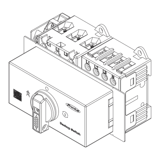
Page 15: Operating Controls And Connections
Operating controls and connections Switch positions The backup switch has three switch of the Backup positions: Switch Grid operation The power is supplied by the public grid. 0-position (de-energized) The power supply is safely dis- connected from the public grid or from the backup power sup- ply. -
Page 17: Installation And Startup
Installation and Startup... -
Page 19: Requirements For Connecting The Backup Switch
Requirements for connecting the Backup Switch Protective cir- For safe operation of the Fronius Backup Switch, the following components must cuit be installed in the switch cabinet: Upstream overcurrent protection according to the information in the chapter Technical data on page 35. - Page 20 Load disconnect- Load disconnect- Auxiliary con- or 63 A or 20 A tact switch Tightening torque 2 - 4 Nm 0.8 - 1.7 Nm 0.8 - 1.4 Nm Conductors per ter- minal...
-
Page 21: Preparing For The Installation
Preparing for the installation Safety WARNING! Danger due to short circuits resulting from foreign bodies in the connection area. An electric shock can lead to serious injury or death. ▶ Keep foreign objects away from the connection area or remove them if ne- cessary. -
Page 22: General Disconnection Of The Power Supply
Switch off the battery connected to the inverter. Wait for the capacitors of the inverter to discharge (2 minutes). Installation The Fronius Backup Switch can be mounted on a 35 mm DIN rail. Housing dimensions according to DIN 4388: 7.2 TE (horizontal pitch) with left... -
Page 23: Disassembly Of The Switch And The Housing Cover
Disassembly of Before connecting the cables, the housing cover must be removed. the switch and the housing cov- Set the switch to position "0". Push the switch lock down. ü The switch is now unlocked. Remove the screw. The switch and housing cover can ü... -
Page 24: 1-Pin Installation
1-pin installation Connecting the WARNING! Backup Switch 1-pin to the pub- Danger from loose and/or incorrectly clamped single conductors in the termin- lic grid This can result in severe personal injury and damage to property. ▶ Check that the single conductors are secure in the terminal. ▶... -
Page 25: Connecting Load 1-Pin In The Backup Power Circuit To The Backup Switch
Connecting load WARNING! 1-pin in the backup power Danger from loose and/or incorrectly clamped single conductors in the termin- circuit to the Backup Switch This can result in severe personal injury and damage to property. ▶ Check that the single conductors are secure in the terminal. ▶... -
Page 26: 3-Pin Installation
3-pin installation Connecting the WARNING! Backup Switch 3-pin to the pub- Danger from loose and/or incorrectly clamped single conductors in the termin- lic grid This can result in severe personal injury and damage to property. ▶ Check that the single conductors are secure in the terminal. ▶... -
Page 27: Connecting Load 3-Pin In The Backup Power Circuit To The Backup Switch
Connecting load WARNING! 3-pin in the backup power Danger from loose and/or incorrectly clamped single conductors in the termin- circuit to the Backup Switch This can result in severe personal injury and damage to property. ▶ Check that the single conductors are secure in the terminal. ▶... -
Page 28: Connecting The Data Communication Cables
WSD IN+ TS 5kA-3 TS 100A-1 Wire the Fronius Smart Meter IP via Modbus so that the signal can be inter- rupted. The Fronius Smart Meter IP must not be connected to the network. Description of Feedback switch in backup power position (IN6/IN7) -
Page 29: Mounting The Protective Cover
Mounting the protective cover Mounting the WARNING! protective cov- Danger due to electrical voltage from missing or incorrectly fitted protective covers. Electric shocks can be fatal and/or cause serious property damage. ▶ Fit the protective covers immediately after installing the live cables ▶... -
Page 30: Mounting Housing Cover And Switch
Mounting housing cover and switch Mounting the Reinstall the housing cover and the housing cover switch and secure with the screw. and the switch... -
Page 31: Commissioning
Commissioning Putting the PV Switch on the battery connected to system into op- the inverter. eration Set the DC disconnector to the "on" switch position. Turn on the automatic circuit breaker. General IMPORTANT! Settings in the "Device configuration" → "Functions and I/Os" menu item may only be implemented by staff trained to do so! The service password must be entered for the... -
Page 32: Testing Backup Power Mode
During ongoing operation (recommendation: at least once a year) For test mode, a battery charge of min. 30% is recommended. A description on how to run test mode can be found in the backup power check- list (https://www.fronius.com/en/search-page, item number: 42,0426,0365). -
Page 33: Appendix
Appendix... -
Page 35: Technical Data
Technical data Technical data Load dis- Load dis- Auxiliary connector connector contact Technical data 63 A 20 A switch Thermal rated operating current open I 63 A 20 A 10 A encapsulated I 63 A 20 A 690 V 690 V 690 V Rated insulation voltage U Breaking capacity I... -
Page 36: Service, Warranty Terms And Conditions, And Disposal
Service, warranty terms and conditions, and dis- posal Maintenance Maintenance and service work may only be carried out by Fronius-trained service technicians. Disposal Waste electrical and electronic equipment must be collected separately and re- cycled in an environmentally sound manner in accordance with the European Dir- ective and national law. -
Page 37: Circuit Diagrams
Circuit Diagrams... -
Page 39: Manual Switch To Backup Power 1-Pin Separation, E.g., Australia
Manual switch to backup power 1-pin separation, e.g., Australia Circuit diagram... -
Page 40: Manual Switch To Backup Power 3-Pin Separation, E.g., Austria
Manual switch to backup power 3-pin separation, e.g., Austria Circuit diagram...
Need help?
Do you have a question about the 1P-63A and is the answer not in the manual?
Questions and answers