
Subscribe to Our Youtube Channel
Summary of Contents for SIGRIST SICON M
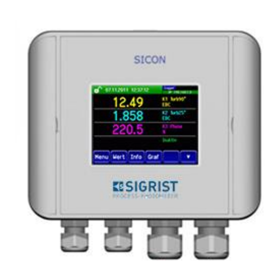
- Page 1 Document number: 11775E Version: 3 Valid from: SW V129 INSTRUCTION MANUAL SICON M Multi-Channel Control Unit...
- Page 2 Copyright© SIGRIST-PHOTOMETER AG, subject to technical changes without notice 8/2019 SIGRIST-PHOTOMETER AG Tel. +41 41 624 54 54 Hofurlistrasse 1 +41 41 624 54 55 CH-6373 Ennetbürgen info@photometer.com Switzerland www.photometer.com...
-
Page 3: Table Of Contents
Designation of the Powerbox ..............14 Scope of supply and accessories..............15 2.3.1 Standard scope of supply for the SICON M ..........15 2.3.2 Optional accessories for the SICON M ............15 Technical data for the SICON M ..............17 2.4.1... - Page 4 General information on connecting the Powerbox ........31 5.10 Safety pointers for the electrical connection ............ 31 5.10.1 Connecting the SICON M to the Powerbox ..........32 5.11 Connecting the field bus interfaces (optional) ..........34 5.11.1 Overview of Profibus DP and Modbus RTU ..........34 5.11.2...
- Page 5 Contents Instruction Manual SICON M 10.2 Warning messages and effect on operation ............ 71 10.3 Fault messages and effect on operation ............73 10.4 Prioritized fault messages and their effect on operation ........75 11 Customer service information ..................77 12 Decommissioning/Storage ...................
- Page 6 Instruction Manual SICON M Contents This pa ge is inte ntionally bla nk 11775E/3...
-
Page 7: General User Information
Purpose of the Instruction Manual This Instruction Manual provides the user with helpful information about the entire life cycle of the SICON M and its peripheral devices. Before commissioning the instrument, you should be completely familiar with the Instruction Manual. -
Page 8: Order Document
The most recent version of this document can be downloaded at www.photometer.com (first time registration required). It can also be ordered from a SIGRIST representative in your country ( Instruction Manual “Customer service information”). Proper use The SICON M is a multi-channel control unit for connecting up to eight instruments. -
Page 9: Dangers When Not Used Properly
The instrument is not properly mounted, set up or transported. The instrument is not installed and operated in accordance with the Instruction Manual. The instrument has been operated with accessory parts which SIGRIST-PHOTOMETER AG has not expressly recommended. Improper changes to the instrument have been performed. -
Page 10: Meaning Of The Pictograms
1.14 Meaning of the pictograms All pictograms used in this document are explained below: Additional information about the current topic. Practical procedures when working with the SICON M. Manipulations on the touchscreen. The screenshot is an example and may differ from current device. -
Page 11: Instrument Overview
Matching resistor set in the photo- meter A maximum of two photometers can be connected to the SICON M directly. The cable length between PM1, SICON M and PM2 must not exceed 800 meters. For cable lengths of more than 5 meters (standard cable length of the photometer), we rec- ommend using a junction box. -
Page 12: Operation Via An Active Conn-A Connection Box
Matching resistor switched on for each photometer 1 .. 8 Eight sensors/photometers can be connected on the SICON M using the active Conn-A con- nection box. The maximum cable length between a sensor/photometer and the active Conn- A connection box is 800 meters. Each of the eight connections is equipped with its own in- terface driver. -
Page 13: Designation Of The Components
Instrument overview Instruction Manual SICON M Designation of the components 2.2.1 Designation of the SICON M The SICON M control unit is fitted with the following rating plate: Figure 3: Designation of the SICON M Manufacturer Country of origin ... -
Page 14: Designation Of The Powerbox
Instruction Manual SICON M Instrument overview 2.2.2 Designation of the Powerbox The Powerbox is fitted with the following rating plate: Figure 4: Designation of the Powerbox Manufacturer Country of origin Product name Serial number ... -
Page 15: Scope Of Supply And Accessories
Instrument overview Instruction Manual SICON M Scope of supply and accessories 2.3.1 Standard scope of supply for the SICON M PCS. ART. NO. NAME VIEW VARIANT 119040 SICON M: 24 VDC multi-channel control unit Documentation: PCS. ART. NO. NAME VIEW... - Page 16 Instruction Manual SICON M Instrument overview PCS. ART. NO. NAME VIEW VARIANT 109534 Connection box 65 x 50 x 35 mm for SIREL / SICON 119045 24 VDC mains de- IP66 protection vice 20 W, input 100 to 240 VAC/47 to 63...
-
Page 17: Technical Data For The Sicon M
Instrument overview Instruction Manual SICON M Technical data for the SICON M 2.4.1 Technical data for the SICON M SICON M DATA VALUES Dimensions 160 x 157 x 60 mm Service voltage 9 .. 30 VDC Power consumption Display ¼ VGA with touchscreen Resolution: 320 x 240 pixels with 3.5"... -
Page 18: Technical Data For The Powerbox
Instruction Manual SICON M Instrument overview 2.4.3 Technical data for the Powerbox DATA VALUES Usage System expansion with 12 relays and 4 digital inputs Dimensions Approx. 255 x 200 x 90 mm (W x H x D) Service voltage 100 .. 240 VAC, 47 .. 63 Hz or 24 VDC Power consumption Max. -
Page 19: General Safety Points
Registered users can download the current version at www.photometer.com. Moisture and condensation on electronic components during operation. Damage may occur if moisture enters the inside of the SICON M. CAUTION! Penetration of moisture as well as condensation on the electrical components dur- ing servicing duty. -
Page 20: Residual Risk
Instruction Manual SICON M General safety points Residual risk According to the risk assessment of the applied safety directive DIN EN 61010-1, there remains the risk of the displayed measuring values being incorrect. This risk can be reduced with the following measures: ... -
Page 21: Preventing Undesirable Online Access Attempts
Instruction Manual SICON M Preventing undesirable online access attempts SIGRIST instruments are equipped with an integrated web user interface and Mod- bus TCP interface, thus offering state-of-the-art administration and control possibil- ities. However, if these are connected directly to the Internet, then any Internet us- er can in principle access your instrument and change the configuration. -
Page 22: Mounting
Instruction Manual SICON M Mounting Mounting Mounting the SICON M WORKSTEP ADDITIONAL INFO / IMAGES Open the shutters. Fasten the control unit to the wall using four screws (circles). 11775E/3... -
Page 23: Electrical Installation
Electrical installation Instruction Manual SICON M Electrical installation Safety pointers for the electrical connection Connecting the service voltage. Improper connection of the service voltage can be potentially fatal. The system may also be damaged. Local regulations for electrical connection must be observed at all times. -
Page 24: Installation Of The Sicon M
Instruction Manual SICON M Electrical installation Installation of the SICON M 5.2.1 Opening the cover on the SICON M WORKSTEP ADDITIONAL INFO / IMAGES Open the shutters. Loosen the fastening screws on the cover. Open the cover. Fasten the cover with the cover clamp. To do this, remove the cover clamp from the park po- sition (X) and fasten the cover in position (Y). -
Page 25: Overview Of The Opened Sicon M Control Unit
Electrical installation Instruction Manual SICON M 5.2.2 Overview of the opened SICON M control unit Figure 5: Overview of SICON M Park position for cover clamp microSD card (card for log data) USB connection Ethernet connection ... -
Page 26: Connecting The Sicon M
Instruction Manual SICON M Electrical installation Connecting the SICON M Figure 6: SICON M terminal block Establish the electrical connections in the following sequence: TERMIN MEANING REMARKS 8 .. 11 Connection of the photometer Terminal Description A maximum of two photometers can GND (ground) be connected directly to terminals 8 .. -
Page 27: Connecting The Optional 24 Vdc Power Supply
Electrical installation Instruction Manual SICON M Connecting the optional 24 VDC power supply Life-threatening voltage due to accidentally released voltage-carrying wires. The wires of the supply connection must be secured with cable ties so that if one wire accidentally becomes loose no other parts can be charged with voltage. -
Page 28: Connecting The Conn-A Connection Box
Instruction Manual SICON M Electrical installation Connecting the Conn-A connection box 5.5.1 Overview of SICON M and Conn-A connection box Figure 8: SICON M and Conn-A connection box, opened DC Power SICON M Powerlink SICON M Terminals 1 .. 3 Terminals 4 .. -
Page 29: Connecting The Conn-A Connection Box
For operation with the Conn-A connection box, the driver IC for the Powerlink must be in- stalled on the plug-in socket in the SICON M (Figure 8, pos. X). This is included in the scope of supply for the Conn-A connection box. The SICON M is powered by the Conn-A connec- tion box and requires no power supply itself. -
Page 30: Connecting The Sensors/Photometers
5 and 6 must first be removed, insulated and stored away. The SICON M and all connected sensors are powered via the 24 VDC power supply. The 24 VDC mains device must have sufficient reserve capacity. -
Page 31: Connecting The Powerbox
Electrical installation Instruction Manual SICON M Connecting the Powerbox 5.9.1 General information on connecting the Powerbox The connection cables between the Powerbox, photometer, control units and external con- nections should be long enough so that there is sufficient freedom of movement when car- rying out servicing duties. -
Page 32: Connecting The Sicon M To The Powerbox
Application: SICON: Expansion of power relay SICON M: Expansion of power relay, valve switching Figure 9: Terminal position when connecting the SICON M to the Powerbox Terminals for Powerlink (terminals Driver IC for the Powerlink 1 .. 7) in the SICON M ... - Page 33 Unused Blue / Unused Unused In the SICON M, install the driver IC for the Powerlink on the plug-in socket (Figure 9, pos. 2). This is included in the scope of supply for the Powerbox. During attachment, pay attention to the orientation of the driver IC. The markings on the socket and IC must match.
-
Page 34: Connecting The Field Bus Interfaces (Optional)
Instruction Manual SICON M Electrical installation 5.11 Connecting the field bus interfaces (optional) 5.11.1 Overview of Profibus DP and Modbus RTU Figure 10: Overview of the Profibus DP and Modbus RTU modules Field bus interface (connection Field bus interface (connection printed printed circuit board) for circuit board) for Modbus RTU. -
Page 35: Connecting The Profibus Dp Or Modbus Rtu
Electrical installation Instruction Manual SICON M 5.11.2 Connecting the Profibus DP or Modbus RTU The terminals on the Profibus DP or Modbus RTU module are assigned as follows: TERMINALS PROFIBUS/ MODBUS FUNCTIONAL DESCRIPTION Ground IN Connection for cable shielding 12 A... -
Page 36: Overview Of Profinet Io
Instruction Manual SICON M Electrical installation 5.11.3 Overview of Profinet IO To connect to the Profinet IO, the Profinet IO module must be integrated in the SICON M. The module has an internal switch and provides two Ethernet ports. -
Page 37: Overview Of Hart
The terminals of the HART module are configured as follows: Terminals HART Functional description mA+ In Must be connected with terminal 13 (mA 1+) of SICON M. mA- In Must be connected with terminal 12 (mA 1-) of SICON M. Shield Cable shielding. -
Page 38: Connecting The Analog Modules (Optional)
Instruction Manual SICON M Electrical installation 5.12 Connecting the analog modules (optional) 5.12.1 Overview of 4-way current output The configuration of the current outputs is described in the Section 8.5. Figure 13: Overview of the 4-way current output module ... -
Page 39: Overview Of The 4-Way Current Input
Electrical installation Instruction Manual SICON M 5.12.3 Overview of the 4-way current input The configuration of the current inputs is described in the Reference Handbook. Figure 14: Overview of the 4-way current input module 4-way current input Terminals 5.12.4 Connecting the 4-way current input... -
Page 40: Commissioning
Proceed with the initial start-up in accordance with the following table: WORKSTEP ADDITIONAL INFO / IMAGES Ensure that the SICON M and all photometers are correctly mounted and connected. Switch on the matching resistors in the two ter- Section 2.1.2 minal devices. - Page 41 Commissioning Instruction Manual SICON M WORKSTEP ADDITIONAL INFO / IMAGES Set the outputs. Section 8.7 Set the date and time. Section 8.8 Make the individual settings on the connected Consult the Instruction Manual photometers (Sensor 1 .. 8 menu). of the respective instrument.
-
Page 42: Operation
Instruction Manual SICON M Operation Operation Operation basics In this document we describe the practical examples only for the first steps of the menu con- figuration. All other setting options are described in the Reference Handbook. Operation us- ing the web user interface is described in detail in the Reference Handbook. -
Page 43: Control Elements In Measuring Mode
Operation Instruction Manual SICON M Control elements in measuring mode Figure 15: Control elements in measuring mode Menu button Valu button Enter the menu. Section 7.3 Numerical representation of the meas- uring values. Section 7.4 Info button Diag button Displays the information screen. -
Page 44: Menu Button
Instruction Manual SICON M Operation Menu button Pressing the Menu button and entering the access code takes you to the menu structure. Now the instrument is in service mode. Operator prompting in service mode is described in Section 7.10. Valu button Pressing the Valu button displays the measuring values in numerical form. -
Page 45: Info Button
Operation Instruction Manual SICON M Info button When you press the Info button, a general overview of the instrument settings appears. These settings are described in the following chapters. 7.5.1 Page 1, Info button Figure 16: Info screen, page 1 ... -
Page 46: Info Button
Instruction Manual SICON M Operation 7.5.2 Page 2, Info button Figure 17: Info screen, page 2 Contact information Display of up to 5 pending fault mes- sages 11775E/3... -
Page 47: Info Button
Operation Instruction Manual SICON M 7.5.3 Page 3, Info button The state of all connected sensors is displayed here. Figure 18: Info screen, page 3 Sensor name Serial numbers of the corresponding sensor Fault message Section 10... -
Page 48: Diag Button
Instruction Manual SICON M Operation Diag button When pressing the Diag button, a diagram appears which graphically shows the measuring values over a certain period of time. Figure 19: Graphic representation of the measuring values Graphic representation of the... -
Page 49: Functions Of The Log Screen (Log Button)
Operation Instruction Manual SICON M Functions of the log screen (Log button) The screen logger works independently of the data logger, which is set in the Logger menu and writes to the microSD card. The screen logger records the data of the last 32 days in one-minute intervals. The data can be called up from the Log menu. -
Page 50: Displays In Measuring Mode
Instruction Manual SICON M Operation Displays in measuring mode Figure 21: Displays in measuring mode Measuring value(s) Status line For values which are greater than In measuring mode, the status line is the maximum measuring range, no green and shows the date and time. -
Page 51: Lock / Unlock The Touch Screen
Operation Instruction Manual SICON M Lock / unlock the touch screen MANIPULATION Press the lock icon top left. Within one second press the key bottom at the outside right. Depending on the initial state, the lock icon changes as follows:... -
Page 52: Switching To Service Mode
Instruction Manual SICON M Operation 7.10 Switching to service mode The system is configured in service mode. The measuring procedure is interrupted and the main menus appear on the display. Proceed as follows to access service mode: MANIPULATION ADDITIONAL INFO / IMAGES Press the Menu button. -
Page 53: Control Components In Service Mode
Main menus Next page All functions of the SICON M and in- terfaces are configured in the Local …… menu. Depending on the integrated sensors, the corresponding menus S 1 .. 8 (sensor 1 .. 8 ) appear here. -
Page 54: Numerical Entry
Instruction Manual SICON M Operation 7.11.2 Numerical entry The following screen is for entering numbers and data: Figure 23: Numerical entry Parameter name Entered values Prefix: For entering very large or Numerical entry very small values. This can be done as follows: 1. -
Page 55: Single Selection Of Functions
Operation Instruction Manual SICON M 7.11.3 Single selection of functions The single selection is identifiable by the ESC button in the lower right corner. The currently selected function is green. Use the Up/Down arrows to navigate the options in long lists. -
Page 56: Settings
Instruction Manual SICON M Settings Settings Setting the operating language MANIPULATION ADDITIONAL INFO / IMAGES Press the Menu button. Enter the access code and confirm with OK. Factory setting is 0. Press the Local ……. button. Press the Configuration button to access lan- If the desired menu does not guage selection. -
Page 57: Assigning Slave Numbers Without Conn-A
Settings Instruction Manual SICON M Assigning slave numbers without Conn-A Each individual instrument must have an assigned slave number so that the photometer can be recognized by SICON M. MANIPULATION ADDITIONAL INFO / IMAGES Press the Menu button. Enter the access code and confirm with OK. -
Page 58: Assigning Slave Numbers With Conn-A
Instruction Manual SICON M Settings Assigning slave numbers with Conn-A An automatic search must be started so that the photometers can be recognized by SICON M. MANIPULATION ADDITIONAL INFO / IMAGES Press the Menu button. Enter the access code and confirm with OK. -
Page 59: Setting The Measuring Channels And The Display
Settings Instruction Manual SICON M Setting the measuring channels and the display Setting of which channel should display the connected instruments MANIPULATION ADDITIONAL INFO / IMAGES Press the Menu button. Enter the access code and confirm with OK. Factory setting is 0. - Page 60 Instruction Manual SICON M Settings MANIPULATION ADDITIONAL INFO / IMAGES Select the source of the measuring channel from the Source menu item. This name is dis- played to simplify identification of the measur- ing channel. The source defined under Channel 1 is displayed in the operation display at the top.
-
Page 61: Setting The Current Outputs
Settings Instruction Manual SICON M Setting the current outputs MANIPULATION ADDITIONAL INFO / IMAGES Press the Menu button. Enter the access code and confirm with OK. Factory setting is 0. Press the Local …… button. Press the Curr. outputs button. -
Page 62: Setting The Limits
Instruction Manual SICON M Settings Setting the limits MANIPULATION ADDITIONAL INFO / IMAGES Press the Menu button. Enter the access code and confirm with OK. Factory setting is 0. Press the Local …… button. If the desired menu does not appear, press the arrow at the bot- tom right. -
Page 63: Upper And Lower Threshold Value Of A Limit
Settings Instruction Manual SICON M 8.6.1 Upper and lower threshold value of a limit A maximum of eight limits with upper and lower threshold can be programmed. If the operating mode is set to Exceeded (Figure 26), then while the upper threshold is... -
Page 64: Setting The Outputs
Instruction Manual SICON M Settings Setting the outputs MANIPULATION ADDITIONAL INFO / IMAGES Press the Menu button. Enter the access code and confirm with OK. Factory setting is 0. Press the Local …… button. Press the Inp./outputs button. If the desired menu does not appear, press the arrow at the bot- tom right. -
Page 65: Setting The Date And Time
Settings Instruction Manual SICON M Setting the date and time MANIPULATION ADDITIONAL INFO / IMAGES Press the Menu button. Enter the access code and confirm with OK. Factory setting is 0. Press the Local ……. button. Press the Configuration button. -
Page 66: Setting Or Changing The Access Code
Enter the access code and confirm with OK. Press the Meas button. Instrument again in measuring mode. A forgotten access code can be cleared only by a SIGRIST service engineer. Enter your personal access code here: 11775E/3... -
Page 67: Back Up Configured Data
Settings Instruction Manual SICON M 8.10 Back up configured data These measures can be of use to the service engineers for service purposes. MANIPULATION ADDITIONAL INFO / IMAGES Press the Menu button. Enter the access code and confirm with OK. -
Page 68: Servicing
If servicing duties are not carried out according to the servicing schedule or non-original SIGRIST spare parts are used, this can lead to damage to the instrument or measuring errors. CAUTION! In this case, SIGRIST-PHOTOMETER AG accepts no warranty claims made by the customer and is not responsible for any subsequent costs. -
Page 69: Changing The Battery In The Sicon M
Local regulations for electrical installations must be observed at all times. DANGER! WORKSTEP ADDITIONAL INFO / IMAGES Interrupt the service voltage to the SICON M. Open the SICON M according to Section 5.2.1. Remove the battery (circle). Insert the new battery. -
Page 70: Troubleshooting
Instruction Manual SICON M Troubleshooting 10 Troubleshooting 10.1 Pinpointing malfunctions DETECTABLE MALFUNCTION MEASURE No reading Check whether the supply voltage is connected. Fault message in the display Analyze the fault message according to Section 10.2 to Section 10.4. -
Page 71: Warning Messages And Effect On Operation
Troubleshooting Instruction Manual SICON M 10.2 Warning messages and effect on operation Warnings indicate an unusual state. WARNINGS If a warning occurs during operation, it has the follow- Warning message from the SICON ing effects: The system continues to operate. However, the measuring results must be evaluated with caution. - Page 72 Instruction Manual SICON M Troubleshooting WARNING DESCRIPTION POSSIBLE CAUSES SENSOR CHECK The automatic sensor check Too much external light in the failed. vicinity of the measuring cell (e.g. sight glass). Instrument open. Defective optics/electronics. Service technician ...
-
Page 73: Fault Messages And Effect On Operation
Instruction Manual SICON M 10.3 Fault messages and effect on operation FAULT If a fault occurs during operation, it has the following Fault message from SICON M: effects: A fault is a malfunction which prevents correct measurement value acquisition. - Page 74 Software is not the most re- when the software version of cent version. In this case, the the SICON M is older than the software of the control unit version of the connected in- must be updated to the most strument.
-
Page 75: Prioritized Fault Messages And Their Effect On Operation
When there is a prioritized fault, the cause of the malfunction is serious. A prioritized fault on the SICON M sets all measur- ing values to 0. A prioritized fault on a sensor/photometer sets the concerned measuring values to 0. - Page 76 Instruction Manual SICON M Troubleshooting The following prioritized fault messages can be displayed: PRIO DESCRIPTION POSSIBLE CAUSES DEFAULT VALUES The default values were load- If no parameters were initial- ized or if all parameters were lost, the default values are loaded.
-
Page 77: Customer Service Information
A current list of all SIGRIST country representatives is available online at www.photometer.com. Please have the following information ready when you contact a SIGRIST service point or customer service: ... -
Page 78: Decommissioning/Storage
Instruction Manual SICON M Decommissioning/Storage 12 Decommissioning/Storage 12.1 Decommissioning the control unit The aim of decommissioning is to prepare the individual components of the system properly for storage. WORKSTEP ADDITIONAL INFO / IMAGES Life-threatening voltage inside the instrument. Connecting the electrical lines is extremely dangerous. -
Page 79: Packaging / Transport / Returning
The original packaging materials should be used for packaging the SICON M if possible. If the original packaging is no longer available, note the following information: ... -
Page 80: Disposal
Instruction Manual SICON M Disposal 14 Disposal Disposal of the control unit and its peripheral devices is to be carried out in compliance with regional statutory regulations. The control units have no environmentally damaging sources of radiation. The materials listed below should be disposed of or recycled as described in the following table:... -
Page 81: Spare Parts List
Spare parts list Instruction Manual SICON M 15 Spare parts list The parts mentioned in this documentation and their article numbers are listed in the follow- ing table: Article number Name Remarks 111834 Battery Section 9.2 11775E/3... -
Page 82: Index
Instruction Manual SICON M Index 16 Index 4-way current input ..........39 Glossary ..............7 4-way current output ........... 38 HART..............37 Access code, set ........... 66 Analog modules ........... 38 Article numbers ............ 81 Improper use ............9 Assigning slave numbers ........ 57, 58 Initial start-up ............ - Page 83 Setting the limits, definition ......... 62 Use restrictions ............8 Setting the outputs ..........64 User requirements ..........8 SICON M ........... 24, 25, 26, 28 Spare parts ............81 Storage ............7, 78 Warning symbols on the instrument ....20 Warnings ............
- Page 84 SIGRIST-PHOTOMETER AG Tel. +41 41 624 54 54 Hofurlistrasse 1 +41 41 624 54 55 CH-6373 Ennetbürgen info@photometer.com Switzerland www.photometer.com...
Need help?
Do you have a question about the SICON M and is the answer not in the manual?
Questions and answers