Advertisement
Features
Operating Range 3.5 Mhz – 54 Mhz (Ham Bands)
Internal Automatic Tuner
RF Auto Band Decoding
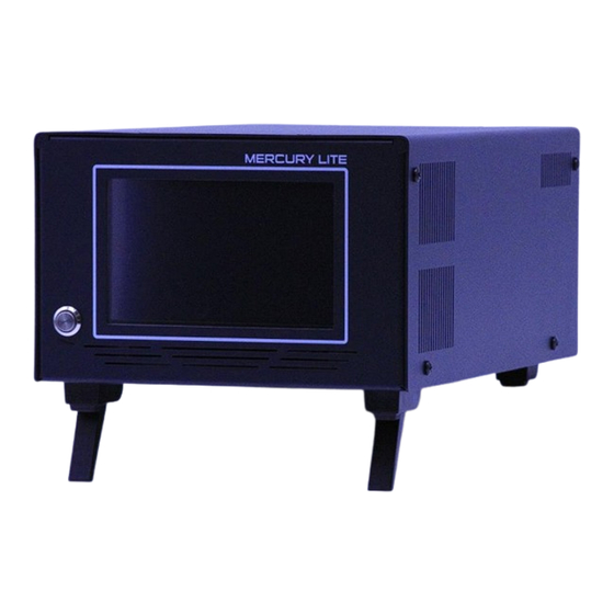
5-inch Color Touch Screen
2 x MRF300 LDMOS
600 Watts all Modes
Input Power 5-40 Watts
FWD/REF/SWR Meter
Supply Voltage / DI Current Meter
All Protections
W 7 x L 11.5 x H 4.5 Inch / Weight 14 Pounds
FCC Approved
MERCURY LITE
USER MANUAL
Designed and Manufactured in the USA
Copyright 2024 KM3KM Electronics LLC.
Advertisement
Table of Contents

Summary of Contents for KM3KM MERCURY LITE
- Page 1 Input Power 5-40 Watts FWD/REF/SWR Meter Supply Voltage / DI Current Meter All Protections W 7 x L 11.5 x H 4.5 Inch / Weight 14 Pounds FCC Approved Designed and Manufactured in the USA Copyright 2024 KM3KM Electronics LLC.
-
Page 2: Table Of Contents
Features & Specs………………………………………………... Page 4 • Quick Start Guide………………………………………………...Page 5 • Main Screen ..…………………………………………………….Page 6,7 • Settings .……………………………………………………………Page 8 • Rear Panel.……………………….……………….……………….Page 9 • Band Test Report…………………………………….……………Page 11 This manual is subject to updates. Check for updated versions at WWW.KM3KM.COM/DOWNLOAD... -
Page 3: Overview
The introduction of the Mercury LITE shows our unwavering pursuit of excellence and our ability to anticipate and fulfill the unmet needs of the industry. With this latest offering, KM3KM will continues to solidify our reputation as a forward-thinking and customer-centric company, ready to set new standards and lead the way in amplifier technology. -
Page 4: Features & Specs
FEATURES & SPECIFICATIONS FEATURES • Low harmonic content (below -43dBc on HF & -65dBc on VHF bands) thanks to an efficient Chebyshev filter. Fast and effective protection systems maintain the amplifier’s safety from operational damage. • • Compact linear amplifier design with (600 Watts) all mode. •... -
Page 5: Quick Start Guide
QUICK START GUIDE 1. Connect the Amplifier to a (48-53 VDC 25-A Source) 2. Connect the output of the Amplifier to a 50-ohm load or to the corresponding antenna. Connect the RF-IN of the amplifier to the RF-OUT of the transceiver. Never connect a Soft-Key 3. -
Page 6: Main Screen
MAIN SCREEN 1. FWD Power Meter: Indicates the output power in operation mode with high accuracy. Note: measurement sometimes will not match with an external instrument due to loss from coax cables loss or other devices connected to the transmission line. This loss can be up to 0.2 dBm. 2. - Page 7 10. OPR/STB: Disables/Enables the amp. The transceiver signal goes directly to the selected antenna when the button is in standby. Standby pass-through power max 100 Watts. 11. Tune Call: Internal Tuner will be ready to receive a 10-30 watts continuous carrier to start the auto adjustment.
-
Page 8: Settings
SETTING SCREEN Main screen / Setup button Sound: Enables or disables the alarm sound. Note: The protections are not disabled. Input 10W: Select ON for the lowest input attenuator for 5-10 Watts drive, ideal for QRP Radios. Select OFF for higher power radios (40 watts MAX). For Safety, when rebooted the selection (Input 10w) will default to OFF. -
Page 9: Rear Panel
REAR PANEL 1. DC Power Input: DC input to feed the Amplifier, the optimum source is 52 VDC 25 Amps. Note that polarity reversal can cause severe damage to the amplifier. 2. SO239 RF Input: Do not exceed an input level of more than 40 Watts. 3. - Page 10 INTERNAL TUNER Internal Tuner Specifications: • Range: 3.5 to 54 Mhz • 600 Watts All modes • Matching Range 3:1 • Tuned 1.3:1 • Inductance 3.33 uH / Capacitance 310 pF • Minimum Tuner Lebel 10 Watts Good Practice. An antenna tuner allows for efficient power transfer by matching the impedance of the transmission line with that of the antenna.
-
Page 11: Band Test Report
GAIN TEST REPORT The following gain tests were run using a terminal design identical to the one currently supplied with this manual. Tolerance range error +/- 0.3 dBm. Equipment test and Procedure. • Driver Exciter - ICOM IC 7300. • Band AT option (OFF) •... - Page 12 DISCLOSURE THIS DEVICE COMPLIES WITH PART 15 OF THE FCC RULES. OPERATION IS SUBJECT TO THE FOLLOWING TWO CONDITIONS: (1) THIS DEVICE MAY NOT CAUSE HARMFUL INTERFERENCE, AND (2) THIS DEVICE MUST ACCEPT ANY INTERFERENCE RECEIVED, INCLUDING INTERFERENCE THAT MAY CAUSE UNDESIRED OPERATION NOTE: THE GRANTEE IS NOT RESPONSIBLE FOR ANY CHANGES OR MODIFICATIONS NOT...
Need help?
Do you have a question about the MERCURY LITE and is the answer not in the manual?
Questions and answers