
Summary of Contents for platypus Mini 30
- Page 1 Operation and Installation Manual Platypus Mini 30 & Mini 50 2 / 27 Binney Road, Kings Park NSW 2148 P – 02 9679 9400 E – info@toyesi.com.au www.toyesi.com.au ABN:33 003 133328 ARC Licence RTA AU02886...
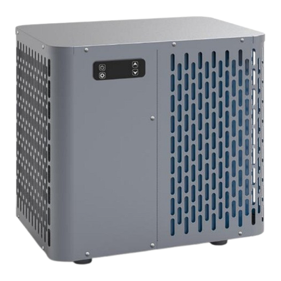
- Page 2 We have produced this manual with the utmost care so that you get maximum benefit from your Platypus Mini heat pump. The Platypus Mini heat pumps are designed for small...
- Page 3 Before Working the Refrigerant Circuit Any intervention on the refrigerant circuit is prohibited without a valid authorisation. Before working on the refrigerant circuit, the following precautions are necessary for safe work. Work procedure The work must be carried out according to a controlled procedure, in order to minimise the risk of presence of flammable gases or vapors during the execution of the works.
- Page 4 Ventilated area Make sure the area is in the open air or is properly ventilated before working on the system or performing hot work. Some ventilation must be maintained during the duration of the work. Controls of refrigeration equipment When electrical components are replaced, they must be suitable for the intended purpose and the appropriate specifications.
- Page 5 PLEASE READ CAREFULLY These installation instructions are an integral part of the product. They must be given to the installer and retained by the user. Always keep the unit upright. If the unit has been tilted or put on its side, wait 24hrs before starting the unit.
-
Page 6: Table Of Contents
Table of Contents 1. DESCRIPTION 1.1 Package contents 1.2 General characteristics 1.3 Technical specifications 1.4 Unit dimensions 1.5 Exploded view INSTALLATION 2.1 Distance from the pool 2.2 Typical configuration 2.3 Hose connection 2.4 Electrical connection 3.1 Wired remote control 3.2 Heating mode 3.3 Cooling mode 3.4 Auto Mode 3.5 Status values and advanced setting... -
Page 7: Description
1. Description 1.1 Package Contents Before starting the installation, please make sure that all parts are found inside the box. The Toyesi Difference... -
Page 8: General Characteristics
1.2 General Characteristics Heat pumps are one of the most economical systems to heat any water efficiently. Using the free renewable energy from the air and the earth it delivers up to five times more energy in heating than a traditional heating system such as gas boiler or electric heater. -
Page 9: Technical Specifications
1.3 Technical Specifications Specification Model Mini 30 Mini 50 Magic Mini 50 Heater/Chiller Heater/Chiller Inverter H/C EVI Heating Range 10 to 40 10 to 40 10 to 40 Cooling Range 8 to 28 8 to 28 8 to 28 Operating Range... -
Page 10: Unit Dimensions
1.4 Unit Dimensions The Toyesi Difference... -
Page 11: Exploded View
1.5 Exploded View The Toyesi Difference... -
Page 12: Installation
2.0 Installation The heat pump is very easy to install, only water and power need to be connected during installation. 2.1 Distance from the pool, tank or body of water. The heat pump should be located at least 2m away from the swimming pool, tank or body of water being heated or cooled. -
Page 13: Hose Connection
2.3 Hose Connection It is normal for condensation water to come out of the heat pump when it is operating. This is not a fault or leak! 2.4 Electrical Connection Make sure your outlet is earthed. The circulation pump must operate with the heat pump. Therefore, it is suggested to connect them to the same circuit used for outdoor. -
Page 14: Use
3.0 Use 3.1 Wired Remote Control SWAPPING MODES Press until you get the correct mode. Red LED heating Mode, Green LED Cooling Mode & Large A on screen for Auto Mode. Whilst in Auto mode LED will swap between green and red depending heating or cooling operation. 3.2 Heating Mode The Toyesi Difference... -
Page 15: Cooling Mode
3.3 Cooling Mode EXAMPLE: If the current temperature is 25°C, default temperature is 27 °C, required temperature is 20 °C. 3.4 Auto Mode EXAMPLE: If the current temperature is 28°C, default temperature is 27 °C, Running Cooling EXAMPLE: If the current temperature is 26°C, default temperature is 27 °C, Running heating The Toyesi Difference... -
Page 16: Status Values And Advanced Setting
Useful Information about how the heating mode works When the incoming water temperature is less than or equal to the required temperature (set point temperature) -X°C, the heat pump will switch to heating mode. The compressor will stop when the temperature of the incoming water is greater than or equal to the required temperature (set point temperature) . -
Page 17: Parameters Table
3.6 Parameters Table The Toyesi Difference... -
Page 18: Operation
4.0 Operation 4.1 Operation Conditions of use For the heat pump to operate normally, the ambient air temperature must be between -10°C and 43°C. Recommendations prior to start-up Before activating the heat pump, please: • Check that the unit is stable. •... -
Page 19: Manintenance And Servicing
5.0 Maintenance and Servicing 5.1 Maintenance and Servicing WARNING: Before undertaking maintenance work on the unit, ensure that you have disconnected the electrical power supply. Cleaning The heat pump’s casing must be cleaned with a damp cloth. The use of detergents or other household products could damage the surface of the casing and affect its properties. -
Page 20: Repairs
6.0 Repairs 6.1 Breakdowns and Faults In the event of a problem, the heat pump’s screen displays a fault symbol instead of temperature indications. Please consult the table opposite to find the possible caused of fault and the actions to be taken. 7.0 Environmental Information This equipment contains fluorinated greenhouse gases covered by the Kyoto Protocol. -
Page 21: Wiring Diagram
9.0 Wiring Diagram Please refer to the wiring diagram on the electric box. The Toyesi Difference...
Need help?
Do you have a question about the Mini 30 and is the answer not in the manual?
Questions and answers