Table of Contents
Advertisement
Quick Links
PRODUCT MANUAL
ver 2024-05-13
SOLAR CONTROLLER
FOR HEATING WATER, BOILERS
GREEN BOOST
4000 BYPASS
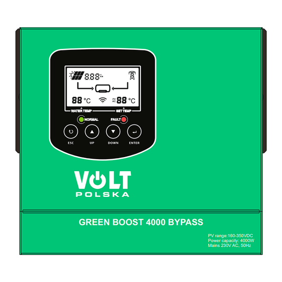
GREEN BOOST 4000 BYPASS
PV range:160-350VDC
Power capacity: 4000W
Mains 230V AC, 50Hz
VOLT POLSKA Sp. z o.o.
ul. Świemirowska 3
81-877 Sopot
www.voltpolska.pl
pomoc@voltpolska.pl | hurt@voltpolska.pl | (58) 500 85 62
Advertisement
Table of Contents

Subscribe to Our Youtube Channel
Related Manuals for Volt Polska GREEN BOOST 4000 BYPASS


Summary of Contents for Volt Polska GREEN BOOST 4000 BYPASS
- Page 1 PRODUCT MANUAL ver 2024-05-13 SOLAR CONTROLLER FOR HEATING WATER, BOILERS GREEN BOOST 4000 BYPASS GREEN BOOST 4000 BYPASS PV range:160-350VDC Power capacity: 4000W Mains 230V AC, 50Hz VOLT POLSKA Sp. z o.o. ul. Świemirowska 3 81-877 Sopot www.voltpolska.pl pomoc@voltpolska.pl | hurt@voltpolska.pl | (58) 500 85 62...
-
Page 2: Table Of Contents
CATALOGUE 1. Important safety instructions ...............1 About the manual ................2 2. Introduction....................3 2.1 Overview..................3 2.2 Appearance feature ..............3 2.3 Datasheet ..................5 2.4 System diagram ................. 7 3. Installation notes ..................8 3.1 Getting started................8 3.2 Installation ...................9 4. -
Page 3: Important Safety Instructions
1. Important safety instructions To ensure your safety, please read the user manual carefully before installing and using the MPPT solar electric heating controller, and keep this manual for future use. The following symbols are used in this manual to indicate potentially hazardous conditions or to mark important safety items. -
Page 4: About The Manual
Do not wear jewelry when installing the controller. The power cord connection must be fastened to prevent the power connector from overheating to catching fire due to the loose power cord. Use wires and circuit breakers of appropriate specifications. About the manual This manual provides detailed installation and operating instructions for the MPPT solar electric heating controller. -
Page 5: Introduction
2. Introduction 2.1 Overview The MPPT solar electric heating controller (hereinafter referred to as the controller) is to provide the electric energy which generated by the solar panel, to the electric heating rod with the maximum efficiency through the MPPT technology. It converts PV direct current into square wave alternating current, which can be used to connect to traditional utility water heaters directly. - Page 6 ①---PV input terminal + Connect PV positive (+) - Connect to PV negative (-) ②---Temperature detection terminal ③---AC OUTPUT terminal interface L------Connected to water equipment L line N------Connect water equipment N line PE-----Ground wire for water equipment ④---AC INPUT terminal interface L-----Connected to AC grid L line N-----Connect to AC grid N line PE----Connect to AC Grid Ground line...
-
Page 7: Datasheet
2.3 Datasheet Rated power 4000W The MPPT water heating controller is only suitable for heating resistance heating components through solar Scope of application power, and the controller load can only be used to connect resistance equipment or AC heaters, heating power within 360V/4000 watts. - Page 8 isn’t less than 13 ohms Machine characteristics Machine dimensions 195*183*100 mm Package dimensions 255*246*158mm Net weigh 2.4 Kg Gross weight 2.75 Kg Ingress Protection IP33 pomoc@voltpolska.pl | hurt@voltpolska.pl | (58) 500 85 62...
-
Page 9: System Diagram
2.4 System diagram 2.4.1 Working principle diagram 2.4.2 System wiring diagram pomoc@voltpolska.pl | hurt@voltpolska.pl | (58) 500 85 62... -
Page 10: Installation Notes
3. Installation notes 3.1 Getting started The installation environment is critical to the performance and service life of the controller. The controller is recommended to be installed in a dry environment and prevent water infiltration. It is best to ensure sufficient ventilation around the controller and sufficient air flow. -
Page 11: Installation
3.2 Installation 3.2.1 Wire diameter selection It is very important to choose a suitable cable diameter for the controller. Generally, at least ensure that the voltage drop of the cable from the controller to the solar panel, the controller to the heating rod, and the controller to the water dispenser is less than 2% of the system voltage. - Page 12 The controller is required to be perpendicular to the mounting surface, If the installation angle deviates from the vertical direction by more than 45 degrees, it will cause poor heat dissipation of the controller, which may affect the power output of the controller. 3.2.3 Wall mounted installation Choose any set of mounting holes, and install the controller vertically on the wall with expansion screws.
- Page 13 Warning: Electric DANGER ! Before removing the wiring cover, please make sure that the controller is disconnected from all power sources, and let the controller stand for more than 5 minutes to ensure that the residual power inside the controller is discharged to a safe level. Any live operation will put the operator in a dangerous situation and may cause damage to the controller.
- Page 14 Warning ! Note that if you choose a heating load that exceeds the rated power, the controller will be damaged! 1. Connect the solar panel + (positive) wire to the PV+ terminal on the controller. Connect the solar panel-(negative) wire to the PV- terminal on the controller.
- Page 15 3.2.6 POWER-ON Warning ! Pay attention to the terminal mark! Connecting the photovoltaic to the AC IN or AC OUT terminal or connecting the AC IN to the photovoltaic connection terminal or connecting the AC IN to AC OUT connection will cause the controller irreversible damage.
- Page 16 3.2.7 POWER-OFF Warning ! Pay attention to the power-off sequence! After ensuring that the AC connected to the controller and the solar panel connected to the controller are completely disconnected, can remove other cables. pomoc@voltpolska.pl | hurt@voltpolska.pl | (58) 500 85 62...
-
Page 17: Operation Instructions
4. Operation instructions After the MPPT controller installed, it will operate smartly. Solar is the first priority source, when solar is insufficient, will switch to AC automatically. 4.1 Maximum power point tracking technology The maximum power point tracking technology can detect the power generated by the solar panel in real time and track the maximum power generated by the solar panel to ensure that the solar cell array can work at the current maximum power point. -
Page 18: Protection Function
stops flashing , setting is complete, or press the esc key , the number stops flashing , setting is canceled. When AC is heated, the water temperature reaches the maximum water temperature of the set AC heating, the AC stops heating, and when the water temperature drops to 3 °C below the maximum water temperature of the set AC heating, the AC cancels to stop heating. -
Page 19: Inspection And Maintenance
260VAC, the Fault indicator will be off, and the controller recovers to operate. PV input voltage high alarm The open circuit voltage of the solar cell array connected to the controller should be less than exceeds the rated maximum value. If the open circuit voltage of the solar cell array exceeds the maximum input voltage specified by the controller, the controller will stop working or even be damaged. - Page 20 4.4.2 Inspection of controller wiring cover Note: Danger of electric shock! Before removing the wiring cover, make sure that all power supplies connected to the controller are disconnected. If the power has not been disconnected, do not open the controller wiring cover. Please open the controller wiring cover 5 minutes after all power is disconnected.
-
Page 21: Common Trouble Shooting
5. Common trouble shooting 1.There is no LED indicator, and the controller appears to have no electrical connection and does not turn on. Solution: Use a multi-meter to measure the voltage across the terminals of the photovoltaic panel of the controller. The voltage of the photovoltaic panel terminal must be above 160 VDC for the controller to operate. -
Page 22: Warranty Service Regulations And Repair Process
6. Warranty service regulations and Repair process 6.1 Warranty service regulations Within 15 months from the date of production, all non-human being performance failures of the controller occurred. Please contact your local dealer to provide warranty service. Non-warranty regulations The following situations (but not limited to the following situations) are not covered by the warranty service: Human being-made damage caused by accident, negligence, improper installation or improper use. -
Page 23: Repair Process
WARRANTY CARD DATE OF PURCHASE SHIPPING ADDRESS SIGNATURE / STAMP DAMAGE DESCRIPTION SERVICE COMMENTS FILL IN IF NEEDEED (*) Cross incorrect I agree to pay the cost of inverter repair due to: * expiration of the warranty period / * warranty void Before proceeding with the repair, service will inform by phone about the exact costs of the repair.
Need help?
Do you have a question about the GREEN BOOST 4000 BYPASS and is the answer not in the manual?
Questions and answers