Advertisement
HEJM Automatisierungstechnik GmbH
Wilhelm-Moriell-Straße 7
D-78315 Radolfzell
Parameter,
Instructions
for device series
DR322
when used as a
syncro controller.
Hardware version DR300_02
Software version DR300_06
Phone: 07732 94558-0
Fax:
07732 94558-29
E-Mail: info@hejm.de
Web:
www.hejm.de
Advertisement
Table of Contents

Summary of Contents for Hejm Automation DR322
- Page 1 Parameter, Instructions for device series DR322 when used as a syncro controller. Hardware version DR300_02 Software version DR300_06 HEJM Automatisierungstechnik GmbH Phone: 07732 94558-0 Wilhelm-Moriell-Straße 7 Fax: 07732 94558-29 D-78315 Radolfzell E-Mail: info@hejm.de Web: www.hejm.de...
- Page 2 Setting up the time-controlled controller52 Serial interface Connecting to the PC Einleitung Introduction Technical Data Functions Format determination 8.6.1 Forward control 8.6.2 Backward control 8.6.3 Data control Send Receive Serial commands 8.10 Status of an axis Illustration Parameterbeschreibung DR312-DR322 Synchronmodul...
-
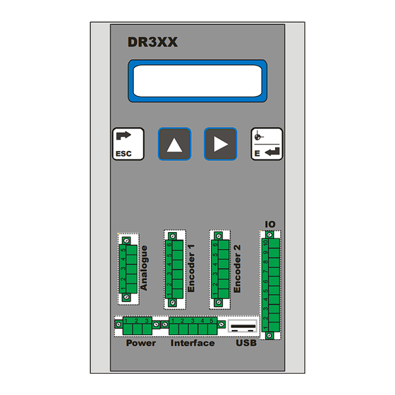
Page 3: Power Interface
Introdution The device series DR312, DR322 can operate in various applications. Parameter P06 is used to adjust the device to the application. Different parameter lists are shown then. When the device is used as a syncro controller, this parameter has to be set in a range between 12 to 14. - Page 4 Signal B Pin 5 Signal Z Pin 6 GND, for shield When brushless DC motors are connected, the rotor position signals can be used as a measuring system too. In this case Con 3 will not be used. Parameterbeschreibung DR312-DR322 Synchronmodul...
- Page 5 Pin 9 Output 1, reserved for future use Pin 10 Output 2, reserved for future use For security reasons both motors are stopped, when a limit switch gets active and the device is used as a synchro controller. Parameterbeschreibung DR312-DR322 Synchronmodul...
- Page 6 CON6 Interface(Interface) Terminal strip 5 pin Pin 1 Can L Pin 2 RS232 RxD Pin 3 RS232 TxD Pin 4 Can H Pin 5 CON7 USB update connector (USB) USB connector Parameterbeschreibung DR312-DR322 Synchronmodul...
- Page 7 Pin 3 Hall sensor C (Motor phase T) Connect this to GND when brushed motors are used. Pin 4 Hall sensor B (Motor phase S) Pin 5 Hall sensor A (Motor phase R) Parameterbeschreibung DR312-DR322 Synchronmodul...
- Page 8 Pin 3 Hall sensor C (Motor phase T) Connect this to GND when brushed motors are used. Pin 4 Hall sensor B (Motor phase S) Pin 5 Hall sensor A (Motor phase R) Parameterbeschreibung DR312-DR322 Synchronmodul...
- Page 9 When two squares are shown, the difference between master and slave is 0. Press to switch to the 4. Information window. The motor current of master and slave are shown here. Parameterbeschreibung DR312-DR322 Synchronmodul...
- Page 10 Parameter The device provides 8 levels . 1. Datuming Master 2. Datuming Slave 3. Parameter level All 4. Parameter level Master 5. Parameter level Slave 6. Factory level 7. Adjust level 8. Test level Parameterbeschreibung DR312-DR322 Synchronmodul...
- Page 11 When is pressed, the datuming function is finished without any changes. When the value appearing on the screen should be changed press once. A blinking cursor is shown on the last decade. Eichen Master Achse1: 100.0 Parameterbeschreibung DR312-DR322 Synchronmodul...
- Page 12 When is pressed, the actual value of the axis is set to the displayed value.. After is pressed the device switches back to operational mode. Parameterbeschreibung DR312-DR322 Synchronmodul...
- Page 13 After was pressed a few times P06 will appear on the screen for example To change the value must be pressed. A blinking cursor is shown on the last decade. Parameterbeschreibung DR312-DR322 Synchronmodul...
- Page 14 Store the parameter to RAM by pressing and the next parameter is shown automatically . When the changed value is out of its limits the minimal or maximal value is shown. Parameterbeschreibung DR312-DR322 Synchronmodul...
-
Page 15: Parameter List
P05 (master or slave level). Parameters which are filled with index ro can only be read. Parameter level All Software version [ro/------,-------] Actual software version of the device. Language [Language/0,1] Setting Language German English Parameterbeschreibung DR312-DR322 Synchronmodul... - Page 16 Axis 2 will follow axis 1 synchron or in the adjusted ratio. The device is used as a synchronization module. The demand value, start and stop commands are sent via the available interfaces. Axis 2 will follow axis 1 synchron or in the adjusted ratio. Parameterbeschreibung DR312-DR322 Synchronmodul...
- Page 17 Data can only be entered in the parameter level All, Axis 1 and Axis2 after entering this code. Security code for datuming level [6 decade number/ 0, 999999] Datuming may be protected against unitended changes by using a security code. Datuming can only be done after entering this code. Parameterbeschreibung DR312-DR322 Synchronmodul...
- Page 18 NC contact by pressing 1. 6 inputs are available using the device as a position controller Up to 64 various combinations are possible with these 6 inputs. The following table gives a more detailed description of the procedure. Parameterbeschreibung DR312-DR322 Synchronmodul...
- Page 19 Input 2 = Limit switch motor 2 negative – BCD Code 4 Input 3 = Limit switch motor 2 positive – BCD Code 8 Input 4 = Limit switch motor 1 negative – BCD Code 16 Input 5 = Limit switch motor 1 positive – BCD Code 32 Parameterbeschreibung DR312-DR322 Synchronmodul...
- Page 20 Example: Input 0, 1, 3, 4 = NO. Binary x Input NC / NO Binary Decimal Decimal Total Enter “356” in parameter All/P70 to get required input configuration Parameterbeschreibung DR312-DR322 Synchronmodul...
- Page 21 Both outputs are switched to tristate when activated Baud rate for serial communication [Baud/ 4800/256000] When the device has a serial interface the baud rate for serial communication must be set here. Setting Baud rate 4800 9600 19200 38400 56000 115200 256000 Parameterbeschreibung DR312-DR322 Synchronmodul...
- Page 22 These parameters are reserved for customized software versions. Analogue offset 0-10V input motor 1 [DAC value/ 0/2047] This parameter is a reserved for customized software versions. Analogue offset 0-10V input motor 2 [DAC value/ 0/2047] This parameter is a reserved for customized software versions. Parameterbeschreibung DR312-DR322 Synchronmodul...
- Page 23 This parameter is used to compensate a temperature offset of the temperature sensor in the drive. Shut down temperature of the drive [°C/ 0/95] The motor drive will be switched of, when it reaches the temperature set here to prevent it from overheating. Parameterbeschreibung DR312-DR322 Synchronmodul...
- Page 24 Only if these specifications are entered in P05 and P06 with no rounding error, will the counter operate correctly over the entire range. Therefore the distance selected should always be one where a whole number of pulses is sent by the encoder . Parameterbeschreibung DR312-DR322 Synchronmodul...
- Page 25 1/10 mm. This means that over a distance of 50 (5.0 mm) 20 pulses are sent by the encoder to the counter. Therefore, set P05 to 50 and P06 to 20. For inch settings, enter P05 in inches. Parameterbeschreibung DR312-DR322 Synchronmodul...
- Page 26 If the time selected is too short, the motor may not dwell at the target point but continue beyond it due to inertia. Parameterbeschreibung DR312-DR322 Synchronmodul...
- Page 27 (ramp value 16000) remains at this speed for a certain period of time before deceleration and reaching standstill (ramp value 8000) The ramp length determines how rapidly the controller should reach its maximum speed. High values lead to long and low values lead to short ramp distances. Parameterbeschreibung DR312-DR322 Synchronmodul...
- Page 28 If P17 is set to 0 , the backlash compensation function is deactivated. Backlash compensation distance [P05/-10000,10000] Exceed demand values on this distance during backlash compensation. The backlash compensation is driven to lower demand values when in the negative range, to higher demand values when in the positive range. Parameterbeschreibung DR312-DR322 Synchronmodul...
- Page 29 Setting = 0 deactivates the D term. Setting = 100 sets the D term to its maximum Feedback monitoring interval [sec/ 0.0001, 5.0000] Measurement period during which the internal demand values and actual values of the controller must agree before it intervenes. Parameterbeschreibung DR312-DR322 Synchronmodul...
- Page 30 Edge counting mode [Edge evaluation/ 4, 4] Here always 4. Counting direction [direction/ 0, 1] Altering this value from 0 to 1, or vice versa, reverses the counting direction of the unit. 0 = forwards 1 = backwards Parameterbeschreibung DR312-DR322 Synchronmodul...
- Page 31 During the time set in this parameter, the controller must get two pulses from the connected measuring system. Otherwise the controller stops the motor and shows an error message. When this parameter is set to 0, the encoder monitoring is switched off. Parameterbeschreibung DR312-DR322 Synchronmodul...
- Page 32 This works constantly against mechanical influences such as pressure and tension. Please note: the motor may overheat due to constant closed loop activity. In certain circumstances, this may lead to faster deterioration or even motor failure. Parameterbeschreibung DR312-DR322 Synchronmodul...
- Page 33 After positioning, if the actual value does not correspond to the demand value ± position window in encoder increments, then the closed loop controller is activated automatically. Within this position window the closed loop control is deactivated. Parameterbeschreibung DR312-DR322 Synchronmodul...
- Page 34 For shorter ramp lengths a lower value must be set to prevent oscillation. This value should not be greater than1% of the ramp length entered in P12 master when running the first trials. If no oscillation occurs, the value can be increased. Parameterbeschreibung DR312-DR322 Synchronmodul...
- Page 35 In case of potential difference between the analogue source and the device it is possible to adjust an analogue range, within an analogue value is interpreted as 0 volt. This will prevent the motor to drift out of its position. Parameterbeschreibung DR312-DR322 Synchronmodul...
- Page 36 During the ramp movement, the control constantly determines the motor's position. If a difference between the setpoint and actual position is detected, the difference is multiplied by the value set here. The result is then added to the PWM output value to compensate the difference. Parameterbeschreibung DR312-DR322 Synchronmodul...
- Page 37 This parameter should be set to 0 when the closed loop function is active. Reserved [---/---,--- ] Parameterbeschreibung DR312-DR322 Synchronmodul...
- Page 38 Software limit switch min. [P05/ -9999999, 9999999] The minimum input value, the device should accept as a demand value. Software limit switch max. [P05/ -9999999, 9999999] The maximum input value, the device should accept as a demand value. Parameterbeschreibung DR312-DR322 Synchronmodul...
- Page 39 Only if these specifications are entered in P05 and P06 with no rounding error, will the counter operate correctly over the entire range. Therefore the distance selected should always be one where a whole number of pulses is sent by the encoder . Parameterbeschreibung DR312-DR322 Synchronmodul...
- Page 40 1/10 mm. This means that over a distance of 50 (5.0 mm) 20 pulses are sent by the encoder to the counter. Therefore, set P05 to 50 and P06 to 20. For inch settings, enter P05 in inches. Parameterbeschreibung DR312-DR322 Synchronmodul...
- Page 41 Edge counting mode [Edge evaluation/ 4, 4] Here always 4. Counting direction [direction/ 0, 1] Altering this value from 0 to 1, or vice versa, reverses the counting direction of the unit. 0 = forwards 1 = backwards Parameterbeschreibung DR312-DR322 Synchronmodul...
- Page 42 Disadvantage: The maximum counting frequency is only 5kHz. The drive will be set automatically to drive a brushless DC motor when this parameter is set to 1. A combination for setting 0 and 1 for the different axis is not possible. Parameterbeschreibung DR312-DR322 Synchronmodul...
- Page 43 Motor rotation direction ( forwards, backwards / 0, 1) This parameter inverts the actual direction of engine rotation. If the motor is rotating in the wrong direction, this parameter must be altered or the cables connecting the motor must be exchanged. Parameterbeschreibung DR312-DR322 Synchronmodul...
- Page 44 I -Gain [Factor/ 0.0000/6.0000] This parameter is used to compensate system deviations, that could not be balanced out by the P-Gain. A large value will cause a fast compensation, but can cause motor vibrations too. Parameterbeschreibung DR312-DR322 Synchronmodul...
- Page 45 Mit diesem Parameter wird der Dezimalpunkt innerhalb der Anzeige gesetzt. 0 = Dezimalpunkt ausgeschaltet 1 = eine Dezimalstelle usw. Die Einstellung des Dezimalpunktes hat keinen Einfluss auf die Auflösung der Anzeige. Diese wird nur mit den Parametern P05 und P06 vorgenommen. Parameterbeschreibung DR312-DR322 Synchronmodul...
- Page 46 P66 Activating start when axis reached target P70 Switching input logic 1 P74 Switching output logic P81 Baud rate for serial communication P82 Device address for serial communication P84 Baud rate for can communication P89 Can device address Parameterbeschreibung DR312-DR322 Synchronmodul...
- Page 47 P08 Number of automatic restart. P09 Tolerance window P10 Drive deactivation 0.20 delay time P11 Maximum ramp 1000 distance for acceleration ramp P12 Maximum ramp 1000 distance for deceleration ramp P13 Fast speed forward and backward Parameterbeschreibung DR312-DR322 Synchronmodul...
- Page 48 P37 Closed loop gain factor 0.0100 P38 Closed loop window P39 Closed loop mode P40 Closed loop P-term P42 Motor rotation direction P52 Invert move direction P53 Analogue input P56 Tolerance range for 0.00 stand still voltage Parameterbeschreibung DR312-DR322 Synchronmodul...
- Page 49 P26 Counting direction P27 Measuring system selection P31 Timer encoder 0.00 monitoring P32 Operating threshold for encoder monitoring P42 Motor direction P60 Relation of correction value P61 P-Gain 0.100 P62 I-Gain 0.0040 P63 Maximum value for 2000 Parameterbeschreibung DR312-DR322 Synchronmodul...
- Page 50 I -Gain P90 Dezimal place Parameterbeschreibung DR312-DR322 Synchronmodul...
- Page 51 The actual values of master and slave must be set to 0 then. Should the slave count in the wrong direction, P26 of the slave must be changed. When this parameter had to be changed, both axis should be set to the same actual value afterwards. Parameterbeschreibung DR312-DR322 Synchronmodul...
- Page 52 2 display increments), set P75 to 1 and increase P76 until the display value changes. Then P74 may need to be slightly reduced. If faster cycle times are needed, reduce P10 and P22 until the target position is reliably reached. Parameterbeschreibung DR312-DR322 Synchronmodul...
-
Page 53: Serial Interface
An RS232 connection consists of at least 3 lines. Receive Data Transmit Data Ground A 9-pin Sub-D female on the PC is used. RxD and TxD must be cross-connected, since the sender of the one device is connected to the receiver of the other device. Parameterbeschreibung DR312-DR322 Synchronmodul... - Page 54 Slaves are not permitted to send by themselves, but rather only when requested by the master. There are three call types for communication between master and slave. • Send • Receive • Broadcast Parameterbeschreibung DR312-DR322 Synchronmodul...
-
Page 55: Technical Data
Technical Data 8 Bit ASCII 9600 Baud 1 Stopbit 1 Startbit Parity (none) Only in some special cases use 7Bit ASCII 9600 Baud 1 Stopbit 1 Startbit 1 Parity bit Parameterbeschreibung DR312-DR322 Synchronmodul... - Page 56 The following transmission control characters are used for indicating the format: STX: Control character Ctrl B (Hex02) Start of Text ETX: Control character Ctrl C (Hex03) End of Text These characters appear only once in the format. All data are sent in ASCII code. Parameterbeschreibung DR312-DR322 Synchronmodul...
- Page 57 The following transmission control characters are used for this: NAK: Control character (Hex15) Not acknowledge (negative reply) ACK: Control character (Hex06) Acknowledge (positive reply) Parameterbeschreibung DR312-DR322 Synchronmodul...
- Page 58 General Level and at least one Axis Level. The various levels are distributed as follows. Data command 20XX General Level (calibration value) Data command 21XX Axis 1 Data command 22XX Axis 2 Data command 23XX Axis 3 Parameterbeschreibung DR312-DR322 Synchronmodul...
- Page 59 These parameters do not become active until the "activate data" command is sent. Example: Send the parameter value P01 (demand value) 100 to a device with Address 11. EOT 11 STX 2101 100 ETX BCC The device responds for a display value with "Ack“ Parameterbeschreibung DR312-DR322 Synchronmodul...
- Page 60 STX C1 C2 C3 C4 EOT In all other cases with "NAK“ Example: Request the display value from a device with Address 11. EOT 11 STX 2100 ENQ The device replies for a display value of 100. STX 2100 100 ETX BCC Parameterbeschreibung DR312-DR322 Synchronmodul...
-
Page 61: Serial Commands
2X52. Example: Start axis 1 EOT 11 STX 2152 128 ETX BCC Start axis 2 EOT 11 STX 2252 128 ETX BCC Start both axis EOT 11 STX 2052 128 ETX BCC Parameterbeschreibung DR312-DR322 Synchronmodul... - Page 62 0x20 Short circuit detected 0x40 Measuring system error 0x80 Limit switch active (not used here) Several combinations of these status bits are possible. For example the meaning of “3” is, that the axis is enabled and running. Parameterbeschreibung DR312-DR322 Synchronmodul...
- Page 63 Illustration Abb. 1 Connection located on the front panel ..........3 Abb. 2 Wiring diagram bottom plate ..............7 Parameterbeschreibung DR312-DR322 Synchronmodul...
Need help?
Do you have a question about the DR322 and is the answer not in the manual?
Questions and answers