Table of Contents

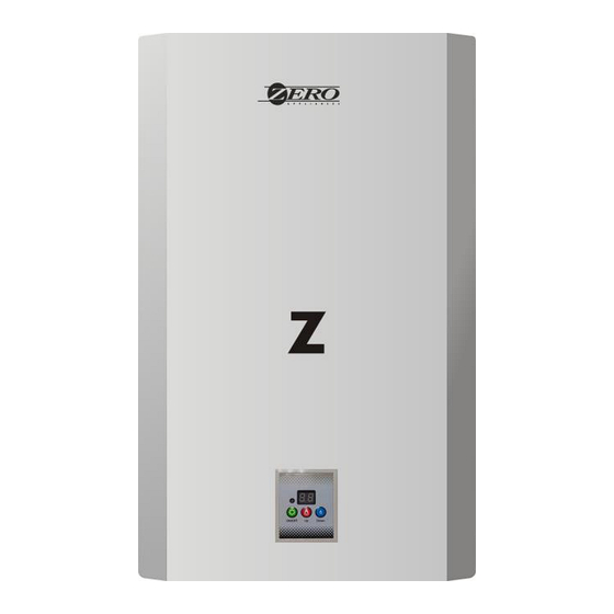
Summary of Contents for Zero Appliances TEMPERATURE CONTROLLED CONTINUOUS FLOW GAS WATER HEATER
- Page 1 TEMPERATURE CONT ROLLED CONTINUOUS FLOW GAS WATER HEATER (18L 3V CONSTANT TEMP) FOR OUTDOOR USE ONLY (TYPE D) INSTRUCTION MANUAL PLEASE READ THIS MANUAL CAREFULLY PRIOR TO INSTALLATION AND USE RETAIN THESE INSTRUCTION FOR FUTURE REFERENCE...
-
Page 2: Table Of Contents
Contents INTRODUCTION AND SAFETY WARNINGS INTRODUCTION AND IMPORTANT SAFETY INSTRUCTIONS SAFETY WARNINGS DESCRIPTION OF THE APPLIANCE SHAPE & NAME OF COMPONENTS MAIN TECHNICAL DATA WIRING DIAGRAMS OPERATION DESCRIPTION OF OPERATION OPERATING INSTRUCTIONS START UP&TESTING INITIAL START UP NORMAL OPERATION 11-13 ROUTINE START UP TEMPERATURE CONTROL PANEL DIAGNOSTIC... -
Page 3: Safety Warnings
IMPORTANT: KEEP THIS MANUAL FOR FUTURE REFERENCE! SAFETY WARNINGS INTRODUCTION AND SAFETY WARNINGS INTRODUCTION DO NOT use a fuel gas that is not listed on the nameplate as compatible DANGER Thank you for purchasing constant temperature controlled continuous Flow Gas with the water heater. -
Page 4: Description Of The Appliance
· Do not over tighten connections or equipment may be damaged. DESCRIPTION OF APPLIANCE · Do not install in areas that are subject to vibration. · This equipment may not be operated without the vent pipe properly connected. The exhaust pipe must not terminate in an area where the exhausting vapor or collecting SHAPE &... -
Page 5: Main Technical Data
MAIN TECHNICAL DATA WIRING DIAGRAMS The installation of this appliance must be carried out by a SAQCC certified Gas Practitioner carried out in accordance to SANS10087-1-2013.(Now in revision) Ignitor Use only a 2.8kPa SANS127 approved regulator with a minimum flow of 3kg/hr. Thermostat Ground wire Mack... -
Page 6: Operation
OPERATING INSTRUCTIONS OPERATION START UP AND TESTING DESCRIPTION OF OPERATION WARNING o Gas Tankless water heaters provide an efficient reliable supply of hot water. WARNING: If the information in these instructions is not followed exactly,a fire or o The temperature can be adjusted between 36C and 65C. explosion may result causing property damage, personal injury or death. -
Page 7: Initial Start Up
Normal Operation INITIAL START UP This section of the manual instructs an owner on routine operating procedures and assumes that 1. STOP! Read the safety information from the previous page. the water heater has already been installed, tested, and approved for operation. Initial start up requirements is detailed in the "Installation"... - Page 8 DIAGNOSTIC CODES Whenever a failure occurs, an alert sounds and a diagnostic code is displayed to indicate the failure mode at the time of occurrence. The following table includes a list of diagnostic codes that can be displayed as well as recommended remedies to address the problem.
-
Page 9: Extended Shutdowns
4.Open all hot water faucets. DANGER 5.Obtain an appropriate container to collect the residual water from the system. Prevent water from being discharged on the floor to avoid damage. NARNIN G Prevent water contact with any electrical source in the vicinity. SCALD PREVENTION o Water temperatures over 52°... -
Page 10: Cold Weather Warnings
INSTALLATION COLD WEATHER WARNINGS INSTALLATION GUIDEUINES Freezing Damage Potential and Precautions Only qualified Gas Practitioner (See warnings) should install this equipment. Improper installation Freezing temperatures can damage the water heater and/or water piping. Freezing water expands or installation by a non-qualified installer will void your warranty. Failure to comply with The rapidly and can create tremendous mechanical forces. -
Page 11: Packing List
PACKING LIST LOCATION AND CLEARANCE REQUIREMENTS The following contents are included. If any items are missing contact Trojan Trading. Quantity Item Water Heater Installation and Operation Manual Gas connector Seal Ring TYPICAL INSTALLATION · Expansion Anchors Minimizing vent piping will reduce installation costs and maximize efficiency. We recommend that a service valve kit be used for the installation as it will reduce installation costs and make servicing the water heater easier. -
Page 12: Mounting
MOUNTING 4.(For installation on Concrete or Block) Drill three each 5/16"(or 8 mm) holes at the marked locations. Insert the supplied X"(6 mm) Steel expansion bolts into the holes. 5.(For wall installation) Locate a stud and use supplied mounting screws or hollow Wall The heater MUST be installed in a vertical position with fuel gas inlet at A nc h or s . -
Page 13: Water Piping
7. After filling and flushing the system, check the inlet water filter for debris and clean as required. 7. Manufacturer recommends installation of gas pressure regulator of 2.8kPa with a minimum flow of 3kg/hr on gas line to ensure gas pressure is at optimum level for proper unit operation. 8. -
Page 14: Maintenance And Inspection
C.Elbow of the vent-pipe should be 90° and not more than 3pcs. MAINTENANCE INSPECTION D.The inner part of the vent-pipe above the wind backwards preventing cover should be more Routine Inspection than 250mm. E. Top of the vent-pipe should be with wind cap to prevent wind, rain and snow. The distance The heater and exhaust piping will be hot during and shortly after use. -
Page 15: Troubleshooting
Clean inside of unit by vacuuming or blowing out dust that collects in the unit. The burner and heat exchange are sealed units and should not be opened. Visual flame inspection Lime scale cleaning(if required), See procedure in Maintenance Procedures that follow. MAINTENANCE PROCEDURES BURNER INSPECTION AND CLEANING... - Page 16 Remedy Trouble Possible Cause Check and fully open water inlet Water source is restricted. Change a new battery valve(s) No power temperature displaying Put the battery in proper position. Battery's position is not right Check and clean inlet water filter No/empty fuel source...


Need help?
Do you have a question about the TEMPERATURE CONTROLLED CONTINUOUS FLOW GAS WATER HEATER and is the answer not in the manual?
Questions and answers