
Summary of Contents for XIMEA XS-5P-U3-UC-TC
- Page 1 • XS-5P-U3-UC-TC Multifunctional USB Hub Ximea accessories • Technical Manual • Version v240830 •...
-
Page 2: About This Manual
The purpose of this document is to provide a description of Ximea accessories and to describe the correct way to install related software, drivers and run it successfully. Please read this manual thoroughly before operating your new Ximea accessories for the first time. Please follow all instructions and observe the warnings. -
Page 3: Table Of Contents
........................13 XIMEA Technical Manual, Version: v240830... -
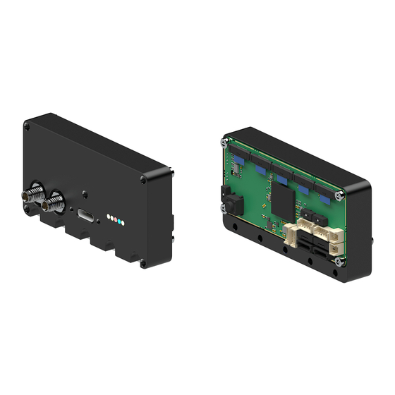
Page 4: General Description
General description Figure 1: isometric view of XS-5P-U3-UC-TC XS ximea switch - Multifunctional USB Hub. UFP (upstream facing port) connector: USB3.2 Gen1, Type-C DFP (downstream facing port) connectors: 5 x USB3.2 Gen1, I-PEX Cabline SS 14pos LEDs Figure 2: LEDs location... -
Page 5: Dimensional Drawings
Dimensional drawings Figure 3: dimensional drawing of XS-5P-U3-UC-TC Width [ W ] Height [ H ] Depth [ D ] Mass [ M ] 70 mm 36.5 mm 22 mm Table 2: parameters XIMEA Technical Manual, Version: v240830... -
Page 6: Configuration
Table 3: DIP switches position In both cases, the trigger signal is distributed across all 5 DFP camera connectors to GPIO1 singal, see image below. Figure 5: I-PEX Cabline SS, 14pos connectors GPIO1 signal scheme XIMEA Technical Manual, Version: v240830... -
Page 7: Connectors
Connectors Location of connectors Figure 6: XS-5P-U3-UC-TC connecotrs location Connector 5 x USB3.2 Gen1, I-PEX Cabline SS 14pos USB3.2 Gen1, Type-C Power connector IO connector Table 4: connectors description Figure 7: I-PEX Cabline SS 14pos ports XIMEA Technical Manual, Version: v240830... -
Page 8: Data Interfaces
SSRX+ SuperSpeed receiver differential pair INOUT1 Non isolated Input/Ouput (<0.3 Low; > 1.3 High) OUT1 Non isolated TTL Output VBUS +5 V Power input VBUS +5 V Power input Table 6: micro-coax connectors pin assignment XIMEA Technical Manual, Version: v240830... -
Page 9: Usb 3.2 Gen1 Type-C
Binder 79 3108 52 04 Table 8: power connector description Figure 10: power connector pinning Name Type Power ground AUX PWR Power supply input AUX PWR Power supply input Power ground Table 9: IO connector pinning XIMEA Technical Manual, Version: v240830... -
Page 10: Io Connector
Binder 77 3550 0000 40003-0x000 (connector on cable side) Table 10: IO connector description Figure 11: IO connector pinning Name Type GPIO_GND Common ground for Input and Output Digital Input (IN) Digital Output (OUT) Table 11: IO connector pin assignment XIMEA Technical Manual, Version: v240830... -
Page 11: Quickstart Guide
Connect CBL-CSS-14-100-50-R1 microCoax cable to the XS-5P-U3-UC-TC Step 3. Connect CBL-CSS-14-100-50-R1 microCoax cable to camera Step 4. Connect USB type-C cable (CBL-U3-P-TC-xM) to the XS-5P-U3-UC-TC Step 5. Connect USB type-C cable (CBL-U3-P-TC-xM) to host (pc) Step 6. Connect IO cable to the XS-5P-U3-UC-TC Step 7. -
Page 12: List Of Figures
List of Figures isometric view of XS-5P-U3-UC-TC .................. -
Page 13: List Of Tables
....................10 XIMEA Technical Manual, Version: v240830... - Page 14 XIMEA GmbH Am Mittelhafen 16 • 48155 Münster • Germany • www.ximea.com © Copyright, XIMEA GmbH, All rights reserved...
Need help?
Do you have a question about the XS-5P-U3-UC-TC and is the answer not in the manual?
Questions and answers