Table of Contents
Advertisement
Quick Links
Advertisement
Table of Contents
Troubleshooting

Summary of Contents for GeD SW2000
- Page 1 SW2000 Twin Point Welder User’s Guide Document Part Number: IM-0068, Rev. A...
- Page 2 SW2000 Twin Point Welders Copyright © GED 2006 IM-0068 Rev A...
- Page 3 SW2000 Twin Point Welder User’s Guide Document P/N: IM-0068, Rev. A Machine S/N:_______________ © 2006 GED Integrated Solutions All rights reserved. All trademarks mentioned in this document are the property of their respective owners. 9280 Dutton Drive Twinsburg, OH 44087-1967 330.963.5401...
- Page 4 SW2000 Twin Point Welders Copyright © GED 2006 IM-0068 Rev A...
-
Page 5: Table Of Contents
Adjusting Heater Plate Stop on the Pneumatic Shift Kit ..............4-9 Limiters and Fence Settings ......................4-10 Adjusting Limiters and Fences.......................4-11 Fixture Settings..........................4-13 Adjusting the Fixture Cam ......................4-13 Testing Fixtures for Slipping ......................4-16 Contents - 1 SW2000 Twin Point Welders Copyright © GED 2006 IM-0068 Rev A... - Page 6 Environmental Conditions ......................5-20 Material Quality ..........................5-21 Pre-cut Material Guidelines .....................5-21 Cut Material Guidelines ......................5-21 Weld Quality ..........................5-22 Testing the Weld........................5-22 Strength .............................5-24 Aligned Corners ........................5-25 Dimensions Correct ........................5-26 2 - Contents SW2000 Twin Point Welders Copyright © GED 2006 IM-0068 Rev A...
-
Page 7: Chapter 1 Overview
Overview This manual contains important information necessary for the proper installation, service, and use of the SW2000 Twin Point Welder product line. Additional custom modifications are available on the SW2000, but may not be covered in this manual. This chapter includes important information about the SW2000 welders including technical specifications, safety considerations and general theory. -
Page 8: Introduction
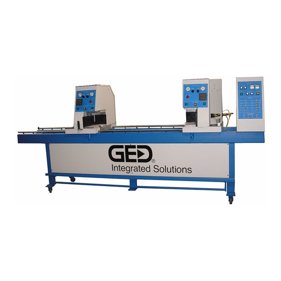
The SW2000 Twin Point Welder combines simple operation and reliable performance to provide accurate welding of vinyl window frames and sashes. The SW2000 enables you to weld up to four corners (two units) per cycle with the optional bi-level stack fixturing. - Page 9 The following photograph shows the basic layout of the SW2000 Twin Point Welder. Because there are many options available, the structure shown below may vary slightly from your machine. Main Control Console Auto Head Manual Head Emergency Stops Station Position Handle...
-
Page 10: Technical Specifications
Full Load Amperage Draw 20 AMP @ 240 VAC 10 AMP @ 480 VAC Compressed Air Requirement 4 CFM @ 90 PSI Heater Plate Wattage 1400 Watts 1-4 • Overview SW2000 Twin Point Welders Copyright © GED 2006 IM-0068 Rev A... -
Page 11: Safety Considerations
If you have any questions or concerns about your equipment, contact GED Customer Service at (631) 231-1900 for additional information. Warning • Pinch Points, and Sharp Edges are present! Keep all body parts safely clear of Pinch Points and Sharp Edges. - Page 12 All moveable parts and assemblies of this equipment must be operated with care and inspected routinely in accordance with the manufacturer's recommendations. Always use genuine GED replacement parts Warning Serious injury or death can be caused by the following: • Sudden, unexpected startup of the machinery or equipment.
-
Page 13: Safety Labels
Keep the labels clean. Wipe away dirt with a soft cloth. If a label is damaged, or fades, or can no longer be easily read, promptly contact GED to obtain a replacement label. Compare the new label to the old Applying Replacement Labels - label, make sure the new label is the correct label. -
Page 14: Safety Guards And Devices
Safety Guards and Devices To provide a safe working environment for operators, the SW2000 welder is equipped with the following safety features: • Two-handed Cycle Start Control - Requires the operator to simultaneously press the two widely-spaced Cycle buttons to start the heating stage of the cycle. -
Page 15: Chapter 2 Installation
Installation This chapter describes how to prepare your SW2000 welder for installation and connection of the electrics and pneumatics. Introduction Inspect the equipment right away. If there is any damage, notify the carrier immediately. GED thoroughly tests all equipment before shipping. The machine may be partially disassembled for safe shipment. -
Page 16: Important Notes
Retain them for future reference. Note: It is the responsibility of the purchaser to secure and fasten objects to floors, walls, ceilings, and other structures. GED assumes no liability for the durability of any such connection, anchor, or fastener, nor for any damage that may result from the installation of any connection, anchor, or fastener. -
Page 17: Preparing For Installation
Note: The consequences of using this equipment with an electrical service (including voltages) that fails to conform to these specifications is the responsibility of the purchaser. GED assumes no liability for equipment damage, malfunctions, nor for any consequences of damage or malfunction due to improper electrical service (including voltages). -
Page 18: Positioning The Equipment
9. Ensure the machine is properly anchored to prevent vibration during operation. If necessary, place shims under the machine legs to level it. 2-4 • Installation SW2000 Twin Point Welders Copyright © GED 2006 IM-0068 Rev A... -
Page 19: Making Electrical Connections
Confirm the code requirements in your area before performing the electrical installation steps. If the safety codes in your area require a different set up, alert GED before installation and document this on the installation layout diagram. Keep this information for future reference. -
Page 20: Making Pneumatic Connections
Welding Pressure gauges to 30-34 PSI. Both gauges are located on the front control panel of the head. Testing the Installation As a final check of the installation, GED recommends that you test the machine to ensure the electrical and pneumatic connections have been correctly made. - Page 21 5. Run a cycle and, before it completes, push an Emergency Stop. Verify that all of the components return to their home positions and the Auto Head retracts, enabling you to remove any mishandled pieces. Test complete. Installation • 2-7 SW2000 Twin Point Welders Copyright © GED 2006 IM-0068 Rev A...
- Page 22 2-8 • Installation SW2000 Twin Point Welders Copyright © GED 2006 IM-0068 Rev A...
-
Page 23: Chapter 3 Operation
Operation This chapter describes how to operate the SW2000 welder. Operation • 3-1 SW2000 Twin Point Welders Copyright © GED 2006 IM-0068 Rev A... -
Page 24: Understanding The Welding Cycle
Understanding the Welding Cycle On the SW2000, a cycle consists of five stages: sizing and clamping, burn-off, heating, fusing, and cooling. In the sizing and clamping stage, the operator loads the rear piece and moves the Manual Head so the mitered end of the piece is 1/2” from the edge of the weld table. - Page 25 To weld the remaining two corners, the operator loads the rear piece and turns the partially welded unit around. The process begins again at the sizing and clamping stage. Operation • 3-3 SW2000 Twin Point Welders Copyright © GED 2006 IM-0068 Rev A...
-
Page 26: Switches And Controls
Turn the switch to position the heater plates for welding the head-end or sill-end of a frame. The switch is located on the left side of the Main Control Console. Head/Sill Switch 3-4 • Operation SW2000 Twin Point Welders Copyright © GED 2006 IM-0068 Rev A... - Page 27 • Four Point - The high pressure clamps are applied in the sizing/clamping stage after the low pressure clamps. GED recommends you use this setting, especially when welding large units which have a greater tendency to slip when bumped.
- Page 28 Flashes every 40 cycles to indicate Heater Plate Clean Indicator - that the heater plates require cleaning. Press to lower the heater plates and reset the indicator. Main Control Console 3-6 • Operation SW2000 Twin Point Welders Copyright © GED 2006 IM-0068 Rev A...
- Page 29 The applicable head fault indicator also illuminates. For more information, refer to “Fault Indicators” on page 5-11. Operation • 3-7 SW2000 Twin Point Welders Copyright © GED 2006 IM-0068 Rev A...
-
Page 30: Right And Left Head Controls
Emergency Stops Service Two-Handed Cycle Start Buttons Button (Cycle and Sizing/Clamping) Right Head Controls (Auto Head) Left Head Controls (Manual Head) 3-8 • Operation SW2000 Twin Point Welders Copyright © GED 2006 IM-0068 Rev A... - Page 31 Service - enable you to use three testing modes for troubleshooting or setting up the machine. For more information, refer to “Using Service Mode” on page 4-2. Operation • 3-9 SW2000 Twin Point Welders Copyright © GED 2006 IM-0068 Rev A...
- Page 32 Press instead of the Sizing/Clamping button to initiate the Foot Bar - low and high pressure clamps after loading the side pieces into the machine. Foot Bar Foot Bar 3-10 • Operation SW2000 Twin Point Welders Copyright © GED 2006 IM-0068 Rev A...
-
Page 33: Setting The Temperature
Ensure the temperature you select is appropriate for the profile you are welding. Operation • 3-11 SW2000 Twin Point Welders Copyright © GED 2006 IM-0068 Rev A... -
Page 34: Timing Modes
Note: Refer to the table on page 5-13 for suggested temperature settings. Timing Modes The SW2000 provides two modes that determine how the heating and cooling stages of the cycle are timed: The heating and cooling times are controlled by internal Auto Mode - parameters set up during manufacturing. - Page 35 “0.” Refer to the photograph below. Current Timer Setting Set Timer Display Push to change indicated digit. Setting the Timers As a general guideline, GED recommends the settings shown in the following table. Unit Type Heating Timer Cooling Timer Sashes...
-
Page 36: Operating The Welder
Operating the Welder This section describes how to operate the SW2000 welder. Warning Do NOT attempt to operate the equipment unless ALL safety guards and devices are in place and working properly. ALWAYS wear appropriate safety gear. Caution The heater plates sustain extreme temperatures. - Page 37 The Auto Head moves toward the Manual Head until it reaches the rear piece. There is approximately 2 1/2” of travel on the Auto Head cylinder. d. The Sizing indicator illuminates. Operation • 3-15 SW2000 Twin Point Welders Copyright © GED 2006 IM-0068 Rev A...
- Page 38 The heater plate lowers into position. If your machine is equipped with a pneumatic shift kit, the heater plate lowers and extends to the position you selected in Step 4. 3-16 • Operation SW2000 Twin Point Welders Copyright © GED 2006 IM-0068 Rev A...
- Page 39 22. Remove the welded (three-sided) unit from the machine. 23. Load the rear piece for the second side of the unit and repeat the procedure from Step 8. Operation • 3-17 SW2000 Twin Point Welders Copyright © GED 2006 IM-0068 Rev A...
-
Page 40: Restarting After An Emergency Stop
2. Pull out the Emergency Stop. 3. Wait for the heater plates to reach the required welding temperature. 4. Continue operation starting at Step 8 in the previous section. 3-18 • Operation SW2000 Twin Point Welders Copyright © GED 2006 IM-0068 Rev A... -
Page 41: Chapter 4 Setup And Adjustment
Setup and Adjustment This chapter describes how to make adjustments to the SW2000 cleaner. Warning Serious injury or death can be caused by the following: • Sudden, unexpected startup of the machinery or equipment. • Contact with live electrical circuits. -
Page 42: Using Service Mode
Using Service Mode The SW2000 provides three Service modes that enable you to test and calibrate the machine: • In Mode A, the selected function operates continuously. • In Mode B, also called “Step Mode,” each movement of the machine through a cycle becomes a single step. -
Page 43: Service Mode A
The selected component activates. For example, if you selected the Setting Plates option, the setting plates at both heads will raise from beneath the table and lower continuously. Setup and Adjustment • 4-3 SW2000 Twin Point Welders Copyright © GED 2006 IM-0068 Rev A... -
Page 44: Service Mode B
2. Press the Service button to begin the continuous cycle. 3. To exit Mode C, press Step Reset once; to completely exit Service Mode, press it twice. 4-4 • Setup and Adjustment SW2000 Twin Point Welders Copyright © GED 2006 IM-0068 Rev A... -
Page 45: Disabling Temperature Controllers
MACR and MMCR relays. Serious injury may result from electrocution if you remove the relays while power is running through the machine. MMCR MACR Disabling Temperature Controls Setup and Adjustment • 4-5 SW2000 Twin Point Welders Copyright © GED 2006 IM-0068 Rev A... -
Page 46: Adjusting The Flow Controls
To adjust, loosen the lock nut, and then turn the knurled knob. Location of cushion controls. Raise Flow Control Lower Flow Control Heater Plate Flow Controls (Up and Down Motion) 4-6 • Setup and Adjustment SW2000 Twin Point Welders Copyright © GED 2006 IM-0068 Rev A... - Page 47 The weld table flow controls (shown below) regulate the forward and retract speed of the weld table. Forward Flow Retract Flow Control Control Weld Table Flow Controls Setup and Adjustment • 4-7 SW2000 Twin Point Welders Copyright © GED 2006 IM-0068 Rev A...
- Page 48 The timing of the weld table is programmed internally and cannot be changed. Forward Flow Control Retract Flow Control Optional Pneumatic Shift Kit Flow Controls 4-8 • Setup and Adjustment SW2000 Twin Point Welders Copyright © GED 2006 IM-0068 Rev A...
-
Page 49: Adjusting Heater Plate Stop On The Pneumatic Shift Kit
45º angle of the cut-end on the jamb and sill pieces. Lock Nut Stop Screw Stop on Pneumatic Shift Kit Setup and Adjustment • 4-9 SW2000 Twin Point Welders Copyright © GED 2006 IM-0068 Rev A... -
Page 50: Limiters And Fence Settings
When the machine is in the sizing position, the required distance from the setting plate to the table limiters, clamp limiters, and edges of the fences is 0.125”. 4-10 • Setup and Adjustment SW2000 Twin Point Welders Copyright © GED 2006 IM-0068 Rev A... -
Page 51: Adjusting Limiters And Fences
10. Insert a 0.010” shim between the clamp limiter and fence to ensure there is enough space between them to prevent the clamp limiter from rubbing against the fence during operation. Setup and Adjustment • 4-11 SW2000 Twin Point Welders Copyright © GED 2006 IM-0068 Rev A... - Page 52 12. Slide the clamp limiter to the gauge and tighten the two 5/16-18 cap screws. 13. Remove the gauge and shim. 14. Repeat Steps 11 through 13 for remaining clamp limiter. 4-12 • Setup and Adjustment SW2000 Twin Point Welders Copyright © GED 2006 IM-0068 Rev A...
-
Page 53: Fixture Settings
Grooves for fixture cams. Fixture Cams Setup and Adjustment • 4-13 SW2000 Twin Point Welders Copyright © GED 2006 IM-0068 Rev A... - Page 54 3. Insert a 0.125” gauge between the setting plate and the side fixture, as shown in the photograph below. 0.125” Measuring 0.125” Between Setting Plate and Fixture 4-14 • Setup and Adjustment SW2000 Twin Point Welders Copyright © GED 2006 IM-0068 Rev A...
- Page 55 Location of the cam adjustment screw. Adjusting Fixture Cam 5. Repeat Steps 2 through 4 with the remaining fixtures. Setup and Adjustment • 4-15 SW2000 Twin Point Welders Copyright © GED 2006 IM-0068 Rev A...
-
Page 56: Testing Fixtures For Slipping
Mark here. Testing Fixtures for Slipping 4. Repeat Steps 2 and 3 with the left-hand piece in the Manual Head. 4-16 • Setup and Adjustment SW2000 Twin Point Welders Copyright © GED 2006 IM-0068 Rev A... -
Page 57: Adjusting The Pins
The pins should protrude enough from the fixture to firmly hold the material without damaging the fixture. Pins (Fixture Closed) Setup and Adjustment • 4-17 SW2000 Twin Point Welders Copyright © GED 2006 IM-0068 Rev A... -
Page 58: Adjusting The Leveling Screws
2. Loosen the set screws holding the pin in position. 3. Adjust so that enough of the pin is extended to firmly hold the material. GED recommends that the pins protrude approximately 0.050” from the fixture; however, your fixtures may require a greater or lesser extension of the pins. -
Page 59: Adjusting The Gap On Open Fixture
Tighten the set screw. 3. Manually press the fixture closed. Ensure the cap screw does not protrude from the top of the fixture. Setup and Adjustment • 4-19 SW2000 Twin Point Welders Copyright © GED 2006 IM-0068 Rev A... -
Page 60: Setting Plate Settings
Top edge of S. P. Setting Plate Setting Plate Cylinder Cylinder Adaptor Cylinder Mount Mount Support Setting Plate Setting Plate Setting Plate Cylinder Cylinder Adaptor Setting Plate Assembly 4-20 • Setup and Adjustment SW2000 Twin Point Welders Copyright © GED 2006 IM-0068 Rev A... -
Page 61: Adjusting The Setting Plate Positioning
3. Ensure that the vertical angle from the setting plate to the carriage table is 90º. If the vertical angle is not 90º, contact GED Customer Service for assistance. Setup and Adjustment • 4-21 SW2000 Twin Point Welders Copyright ©... - Page 62 Refer to the photograph below. Lock Nut Turn to change cylinder stop position. Adjusting the Setting Plate Cylinder Stop 4-22 • Setup and Adjustment SW2000 Twin Point Welders Copyright © GED 2006 IM-0068 Rev A...
-
Page 63: Heater Plate Settings
“Limiters and Fence Settings” on page 4-10. Heater Plate Mount Cylinder Mount Rotary Actuator Heater Plate Base Plate Cylinder Plate Adaptor Heater Plate Assembly (Pneumatic Shift Kit Option Shown) Setup and Adjustment • 4-23 SW2000 Twin Point Welders Copyright © GED 2006 IM-0068 Rev A... -
Page 64: Adjusting The Heater Plate Positioning
Shimming Heater Plate Mount 4. Use a C-clamp to hold the shim in position. Ensure the C-clamp is centered on the linear shaft. Do not over tighten. 4-24 • Setup and Adjustment SW2000 Twin Point Welders Copyright © GED 2006 IM-0068 Rev A... - Page 65 Move the shift kit or cylinder support as necessary, and then tighten the screws. Note: For precise measurement 45º of the angle, GED recommends that you use a gauge with a precise 45º angle as shown here. Measuring Angle from Back Clamp Post to Heater Plate Setup and Adjustment •...
- Page 66 If the machine is equipped with a pneumatic shift kit, adjust the stop, as described in “Adjusting Heater Plate Stop on the Pneumatic Shift Kit” on page 4-9. 4-26 • Setup and Adjustment SW2000 Twin Point Welders Copyright © GED 2006 IM-0068 Rev A...
- Page 67 Loosen to adjust horizontal position of heater plate. Pushing the Heater Plate’s Horizontal Position Setup and Adjustment • 4-27 SW2000 Twin Point Welders Copyright © GED 2006 IM-0068 Rev A...
- Page 68 The starting position of the end of the linear shaft is 1/8” from the end of the cylinder plate adaptor, as shown in the photograph below. 1/8” Positioning of the Linear Shaft 4-28 • Setup and Adjustment SW2000 Twin Point Welders Copyright © GED 2006 IM-0068 Rev A...
-
Page 69: Carriage Brake Settings
Controllers” on page 4-5. If the machine has been running, allow sufficient time for the heater plates to cool down. Serious burn injury can result if the heater plate is accidentally touched. Setup and Adjustment • 4-29 SW2000 Twin Point Welders Copyright © GED 2006 IM-0068 Rev A... -
Page 70: Testing The Carriage Brakes
The four 1/4-20 cap screws securing the brake cylinder to the cylinder mount are tight. • The two 1/4-20 cap screws securing the pivot shaft to the carriage table are tight. 4-30 • Setup and Adjustment SW2000 Twin Point Welders Copyright © GED 2006 IM-0068 Rev A... - Page 71 6. Engage the brake. Ensure the brake pads are centered with respect to the rail. If the brakes are not centered, you may need to adjust the carriage brake assembly. Call GED Customer Service for assistance. Setup and Adjustment • 4-31 SW2000 Twin Point Welders Copyright ©...
-
Page 72: Weld Table Assembly Settings
4-5. If the machine has been running, allow sufficient time for the heater plates to cool down. Serious burn injury can result if the heater plate is accidentally touched. 4-32 • Setup and Adjustment SW2000 Twin Point Welders Copyright © GED 2006 IM-0068 Rev A... -
Page 73: Weld Table Limit Switch Settings
Be careful not to touch the limit switch with the gauge. Stop Rail Stop Plate Testing Weld Table Limit Switch Position Setup and Adjustment • 4-33 SW2000 Twin Point Welders Copyright © GED 2006 IM-0068 Rev A... - Page 74 11. Press the Step Reset button to return the machine to the cycle starting position. Then, reinstall the electrical connector to the Sizing Plate solenoid. 4-34 • Setup and Adjustment SW2000 Twin Point Welders Copyright © GED 2006 IM-0068 Rev A...
-
Page 75: Adjusting The Weld Table Limit Switch
3. Tighten the socket head cap screws when the limit switch is positioned correctly. 4. Repeat the test described in "Testing the Weld Table Limit Switch" until you observe the correct result. Setup and Adjustment • 4-35 SW2000 Twin Point Welders Copyright © GED 2006 IM-0068 Rev A... -
Page 76: Weld Table Cylinder Position Settings
Retighten the lock nut. 3. Remove the gauge. Then, disconnect the Sizing Plate solenoid (Valve #1) to prevent the setting plates from raising. 4-36 • Setup and Adjustment SW2000 Twin Point Welders Copyright © GED 2006 IM-0068 Rev A... - Page 77 6. If this dimension is incorrect (by greater than a few thousands), loosen the 5/8-18 lock nut at the rod-end bearing and thread the weld table feed shaft as appropriate. Retighten the 5/8-18 lock nut. Setup and Adjustment • 4-37 SW2000 Twin Point Welders Copyright © GED 2006 IM-0068 Rev A...
- Page 78 4-38 • Setup and Adjustment SW2000 Twin Point Welders Copyright © GED 2006 IM-0068 Rev A...
-
Page 79: Chapter 5 Maintenance And Troubleshooting
This chapter describes how to maintain and troubleshoot your SW2000 welder. Periodic Maintenance Table To keep your SW2000 welder in optimal condition, it is necessary to perform the periodic maintenance described in this section. Caution Lock-out/tag-out the electrical power to the machine when performing any type of maintenance. - Page 80 Console) to clear it of chips and dust. Caution! Do not blow air inside the electrical cabinet. Clean carriage table and surrounding parts. Blow out chips and dust. Monthly 5-2 • Maintenance and Troubleshooting SW2000 Twin Point Welders Copyright © GED 2006 IM-0068 Rev A...
- Page 81 Inspect the entire machine for any loose or broken hardware. Tight or replace, as Annually necessary. Ensure the machine is level and the leveling hardware is tight (if applicable). Annually Replace PLC battery. Annually Maintenance and Troubleshooting • 5-3 SW2000 Twin Point Welders Copyright © GED 2006 IM-0068 Rev A...
-
Page 82: Filter-Regulator-Lubricator (Frl)
Before operating the machine at the start of each shift, ensure the air pressure on the FRL (shown below) is set to 100 PSI. For proper operation of the SW2000, the air pressure must be consistent. Do not increase or decrease the air pressure during operation. To set the air pressure, turn the black knob on the top of the FRL. -
Page 83: Air Pressure Limit Switch
Air Pressure Limit Switch The SW2000 welder requires a consistent air pressure between 90- 110 PSI for proper operation of the machine. The air supply is monitored by a pressure switch (shown below) which immediately stops the machine if the air supply drops below a specified level. You cannot operate the machine until the specified pressure is returned to the machine. -
Page 84: Low Pressure Clamps, Sizing, And Main Air Pressure Gauges
To set the gauge, cycle machine until the low pressure clamps are activated. Sizing Gauge Air Pressure Gauges (Auto Head) 5-6 • Maintenance and Troubleshooting SW2000 Twin Point Welders Copyright © GED 2006 IM-0068 Rev A... -
Page 85: Lubricating The Rail Bearings
Grease Fitting Turn cap screw to adjust bearing positioning. Rail Bearing (Rear Shown) Maintenance and Troubleshooting • 5-7 SW2000 Twin Point Welders Copyright © GED 2006 IM-0068 Rev A... -
Page 86: Replacing Teflon Covering On The Heater Plates
The heater plates sustain extreme temperatures. To prevent severe burn injuries, always allow sufficient time for the heater plates to cool down before handling them. Wear heat-rated gloves. 5-8 • Maintenance and Troubleshooting SW2000 Twin Point Welders Copyright © GED 2006 IM-0068 Rev A... - Page 87 The Teflon is less likely to tear if left slightly loose on the heater plate because the covering will move with the material during operation. Maintenance and Troubleshooting • 5-9 SW2000 Twin Point Welders Copyright © GED 2006 IM-0068 Rev A...
-
Page 88: Replacing Adhesive Teflon Covering
5. Affix the Teflon covering to the heater plate. Using a sharp cutting tool, such as a razor, cut the Teflon to size, following the contour of the heater plate. 5-10 • Maintenance and Troubleshooting SW2000 Twin Point Welders Copyright © GED 2006 IM-0068 Rev A... -
Page 89: Fault Indicators
Fault Indicators The SW2000 has four fault indicators (shown below) to bring your attention to a problem at each head. The Right and Left Head indicators illuminate under the following two conditions: • The heater plate temperature is too high or too low, as indicated by the accompanying temperature fault indicator. -
Page 90: Weld Table Limit Switch Faults
During manufacturing, GED technicians program the temperature controllers to optimize the performance of your SW2000. With the exception of the following, GED recommends you do not change these parameters unless instructed by a GED technician: •... - Page 91 0.0-100% Balance. Pre-positions the proportional band with respect to the setpoint. 0-100% of full scale Anti-reset wind-up. Limits the range where integration occurs. Maintenance and Troubleshooting • 5-13 SW2000 Twin Point Welders Copyright © GED 2006 IM-0068 Rev A...
- Page 92 Changes both the displayed PV value and the measured PV value. • A positive value lowers the temperature. • A negative value raises the temperature. 5-14 • Maintenance and Troubleshooting SW2000 Twin Point Welders Copyright © GED 2006 IM-0068 Rev A...
-
Page 93: Editing The Parameters
Press the Down arrow button to decrease the value. 6. When you are done changing the parameter, press the ENT button to store the change. Maintenance and Troubleshooting • 5-15 SW2000 Twin Point Welders Copyright © GED 2006 IM-0068 Rev A... -
Page 94: Troubleshooting Symptoms And Solutions
Troubleshooting Symptoms and Solutions The following table lists the potential symptoms and possible solutions for troubleshooting the SW2000. For troubleshooting weld quality issues, refer to “Checking Weld Quality” on page 5-20. Symptom Solution • Machine does not advance from With the Main Power Disconnect switch set to OFF, heating stage of the cycle. - Page 95 240 VAC lead at heater plate. damaged lead to heater plate (may have been pinch in hood). bad connection in junction box. a shorted heater plate in respective head. Maintenance and Troubleshooting • 5-17 SW2000 Twin Point Welders Copyright © GED 2006 IM-0068 Rev A...
- Page 96 3-11. • Ensure the lift kit cylinder is working. • Check the condition of the linear shafts, linear bearings, and or/heater plate return spring. 5-18 • Maintenance and Troubleshooting SW2000 Twin Point Welders Copyright © GED 2006 IM-0068 Rev A...
- Page 97 “Limiters and Fence Settings” on page 4-10. • Ensure the fixture settings are correct, as described in “Fixture Settings” on page 4-13. Maintenance and Troubleshooting • 5-19 SW2000 Twin Point Welders Copyright © GED 2006 IM-0068 Rev A...
-
Page 98: Checking Weld Quality
Ensure the material is stored and processed in a clean, dry area. • Ensure compressed air pressure does not fluctuate more than +/- 10%. The SW2000 welder requires a consistent pressure setting of 100 PSI. • Ensure incoming electrical power does not fluctuate more than +/- 10%. -
Page 99: Material Quality
Ensure the cut angles of the mitered ends are cut properly with a 45º horizontal angle and a 90º vertical angle. Refer to the photograph below. 90º 45º Required Material Cut Angles Maintenance and Troubleshooting • 5-21 SW2000 Twin Point Welders Copyright © GED 2006 IM-0068 Rev A... -
Page 100: Weld Quality
SW2000. Testing the Weld When testing the weld on the SW2000, use square material that will weld evenly whether the glazing leg is up or down. Before beginning the test, ensure the material is cut to the correct length and meets specification as described in the previous sections;... - Page 101 The corners are aligned vertically and horizontally. If there are any issues with the completed unit, refer to the following sections for the weld specifications and suggested solutions. Maintenance and Troubleshooting • 5-23 SW2000 Twin Point Welders Copyright © GED 2006 IM-0068 Rev A...
-
Page 102: Strength
Then, decrease the temperature approximately 10º from the burning temperature. To change the heater plate temperature, refer to “Setting the Temperature” on page 3-11. 5-24 • Maintenance and Troubleshooting SW2000 Twin Point Welders Copyright © GED 2006 IM-0068 Rev A... -
Page 103: Aligned Corners
Teflon covering is not damaged or excessively worn. If necessary, replace the Teflon covering, as described in “Replacing Teflon Covering on the Heater Plates” on page 5-8. Maintenance and Troubleshooting • 5-25 SW2000 Twin Point Welders Copyright © GED 2006 IM-0068 Rev A... -
Page 104: Dimensions Correct
The fixtures are slipping. Check the fixtures and ensure material is not slipping, as described in “Testing Fixtures for Slipping” on page 4-16. Correct as necessary. 5-26 • Maintenance and Troubleshooting SW2000 Twin Point Welders Copyright © GED 2006 IM-0068 Rev A... - Page 105 1-3 Teflon covering on 5-8 restarting after 3-18 temperature faults on 5-11 use of 3-9 heating stage description 3-2 timer for (manual mode) 3-5 Index • 1 SW2000 Twin Point Welders Copyright © GED 2006 IM-0068 Rev A...
- Page 106 3-18 Teflon (covering on heater plates) sequence of 3-14 replacing adhesive type 5-10 setting temperature 3-11 replacing non-adhesive type 5-8 setting timers (manual mode) 3-12 2 • Index SW2000 Twin Point Welders Copyright © GED 2006 IM-0068 Rev A...
- Page 107 5-12 limit switch settings 4-33 welder adjustments 4-1 cycle 3-2 layout 1-3 maintenance of 5-1 operating 3-14 switches and controls on 3-4 welding pressure gauge Index • 3 SW2000 Twin Point Welders Copyright © GED 2006 IM-0068 Rev A...
- Page 108 4 • Index SW2000 Twin Point Welders Copyright © GED 2006 IM-0068 Rev A...
Need help?
Do you have a question about the SW2000 and is the answer not in the manual?
Questions and answers