Table of Contents
Advertisement
Quick Links
Advertisement
Table of Contents

Subscribe to Our Youtube Channel
Related Manuals for ZF SCALAR EVO Guard

Summary of Contents for ZF SCALAR EVO Guard
- Page 1 554 090 0xx 0 Installation Guide SCALAR EVO Guard...
-
Page 2: Table Of Contents
Contents Liability ............................5 Installation with EBS ........................5 Installation without EBS ......................5 Product Article Code ........................6 ADR Approval ..........................6 Hardware Description ........................11 Hardware Activation ........................12 Before the Activation ........................ 12 Activation ..........................12 After Activation ......................... 13 Hardware Connections......................... - Page 3 Apache Cold Tracer ........................84 Carrier DataCOLD 500 ......................85 Carrier DataCOLD 600 / Euroscan X3 ..................88 Carrier Direct ..........................91 Connecting the LIN Sensors ......................94 HACCP Certification ......................... 94 Connecting the First Lin Sensor ....................99 Connecting Sensor to Sensor ....................100 Fixing the LIN Sensors ......................
-
Page 4: Liability
(partial) recording of, and an addition to, the practical knowledge of the average installer. The illustrations and specific data of non-ZF Transics products have been checked thoroughly and have been found correct at the time this manual was composed. However, we cannot accept any responsibility for possible adaptations by the manufacturer concerned. -
Page 5: Product Article Code
Product Article Code 554 090 0xx 0 Meaning of the ‘xx’ in the part number: • ‘11’: Orange SIM card • Other configurations will have a different article code. ADR Approval A test report of TÜV (Technischer Überwachungsverein Hessen GmbH) states that 554 090 0xx 0 is compliant with the following ADR trailer types: •... - Page 6 During the entire connection procedure, the voltage must be turned off. SSEMBLY The assembly of the parts must be done using the accessories provided. ZF Transics cannot be held responsible for any errors resulting from the use of other materials. ZF Transics wishes to point out that activities which require welding to the trailer, can cause damage to the electronics of the device.
- Page 7 • The device is visibly damaged. IF THE DEVICE IS VISIBLY DAMAGED, IT MUST BE IMMEDIATELY REPLACED AND SENT BACK TO ZF TRANSICS. All other instructions, notes and regulations in this operation manual must be closely followed. 554 090 0xx 0 Installation Guide_EN...
- Page 8 Installation Flow Steps of the Installation See… Step 1 – Hardware Components Page 10 • Hardware Description Step 2 – Connecting Hardware Page 11 • Hardware Activation • Hardware Connections • Connecting to the TEBS system o WABCO TEBS-D1 PREMIUM o WABCO TEBS-E SUBSYSTEM o WABCO TEBS-E SUBSYSTEM SmartBoard (Not IVTM) o WABCO TEBS-E GIO5...
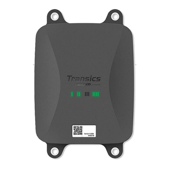
- Page 9 Step 1 – Hardware Components 554 090 0xx 0 is a trailer tracer unit with an embedded SIM card, GSM antenna and GPS antenna. It is designed for outside use and holds a rechargeable battery. It consists of a main unit which can be connected to a trailer’s TEBS system (WABCO, Haldex, Knorr), to a trailer’s reefer recorder unit (Euroscan, DataCOLD, TranScan, TK i-Box, …) or to external (temperature, door, …) sensors.
-
Page 10: Hardware Description
Hardware Description Front view Back view Sensor Reefer EBS EXT1 EXT2 Connections Make sure that the air vent of the Unit is accessible to air at all times. Make sure that nothing can block the air access of the air vent. Side view •... -
Page 11: Hardware Activation
Step 2 – Connecting Hardware Hardware Activation Firstly, the Unit must be activated using a magnet. Upon activation, the Unit will respond using a red and green LED sequence. The start-up sequence of the device can take up to 15 minutes. Before the Activation IMPORTANT When activating a Unit, make sure that it is connected to an external power... -
Page 12: After Activation
After Activation Check the RED sequence of LED 2 for the external power connection status: Blinking Function Color Description Frequency LED 2 External power Battery External power via TEBS connector present External power via reefer connector present External power via TEBS and reefer connector present Leave the Unit on an external power source for at least 15 minutes, so the unit can start up GPRS communication and obtain GPS coverage. -
Page 13: Hardware Connections
Hardware Connections Removing the Safety Caps Before plugging in the connectors, you will need to remove the safety caps from the connection ports. Only remove the safety caps from the ports you will be using. DO NOT REMOVE ANY SAFETY CAPS FROM UNUSED PORTS, AS THE UNIT WILL NO LONGER BE WATERPROOF. - Page 14 3. Finally, press the yellow clip to lock the connection. “Click” k” A distinct “click” should be heard. 4. The connector has been plugged in correctly. Correctly plugged in NOT correctly plugged in 554 090 0xx 0 Installation Guide_EN Confidential Page 15 of 133...
-
Page 15: Connecting To The Tebs System
Connecting to the TEBS System – D MPORTANT IAGNOSTICS OFTWARE Some TEBS systems require parameter adaptation of a specific port. For the parameter adaptation, you will need: • a PC / laptop, • a diagnostics interface, • a connection cable (USB / Serial) •... -
Page 16: Connection To 554 090 0Xx 0
Option 2 Diagnosis in accordance with ISO 11898 (CAN 5 V) via an external diagnosis connection External diagnostics socket with Diagnostics interface (DI-2) CAN diagnostics cable yellow cap (449 611 xxx 0): with USB port (for (446 300 348 0) Only TEBS-E Modulators PC connection) (Premium) - Page 17 PIN Assignment Power EBS Type Article Code Length Available Available 554 090 0xx 0 Side Not compatible with 554 090 0xx 0 WABCO TEBS-D0 Standard Serial number ≤ 75000 Production date ≤ 09/2003 WABCO TEBS-D1 Standard Not compatible with 554 090 0xx 0 480 102 010 0 0942-0388-EBS-01 WABCO TEBS-D1 PREMIUM...
- Page 18 PIN Assignment Power EBS Type Article Code Length Available Available 554 090 0xx 0 Side 0942-0388-EBS-04 WABCO TEBS-E GIO5 V IN 449 030 000 0 480 102 06x 0 Black CAN-H 480 102 08x 0 Brown White CAN-L Haldex EB+ Gen. 1 V in = KL15 0942-0388-EBS-10 V IN...
- Page 19 PIN Assignment Power EBS Type Article Code Length Available Available 554 090 0xx 0 Side Haldex EB+ Gen. 4 554 091 011 0 V IN “842 … …” Green CAN-H “950 800 …” Blue Yellow CAN-L Knorr TEBS4 (G1) ES205x 0942-0388-EBS-06U White V IN...
-
Page 20: Wabco Tebs-D1 Premium
WABCO TEBS-D1 Premium Required Cable 0942-0388-EBS-01 EBS D Connect 554 090 0xx 0 to the IN/OUT port using the TEBS connection cable. Make sure that the contact pins remain clean and dust-free. The modulator parameters do not have to be modified. -
Page 21: Wabco Tebs-E Subsystem
WABCO TEBS-E Subsystem Hardware Connection Required Cable EBS E SUBSYSTEM 0942-0388-EBS-03 In case of a modulator type E (Standard, Premium or Multi-voltage), connect 554 090 0xx 0 to the modulator SUBSYSTEM port using the TEBS connection cable. WABCO TEBS-E Subsystem SmartBoard (Not IVTM) Hardware Connection Required Cable 0942-0388-EBS-07... -
Page 22: Wabco Tebs-E Subsystem Smartboard Ii
WABCO TEBS-E Subsystem SmartBoard II Hardware Connection Required Cable 0942-0388-EBS-07 EBS E SUBSYSTEM SmartBoard II 8946000742 Adapter cable In case a SmartBoard is occupying the SUBSYSTEM port, you will require a specific splitter cable. Connect 554 090 0xx 0 to the modulator Subsystem port using one end of the TEBS connection cable. - Page 23 Parameter Adaptation Using TEBS-E Diagnostics Software Requirements TEBS-E diagnostics software: Consult “Software Requirements - Ordering the Diagnostics Software” p.16. Parameter Adaptation If 554 090 0xx 0 is connected to the SUBSYSTEM slot, telematics must be activated in the TEBS-E diagnostics software as the subsystem: “TEBS window”...
- Page 24 3. Next, select Telematics under “Subsystems” in the “Connector” tab. 4. Press Write to ECU when all modifications have been performed (PIN code needed (cf. “Note” on p. 16)). After connecting all hardware to the Unit, you can check the installation using TX-CONFIG (cf.
-
Page 25: Wabco Tebs-E Gio5
WABCO TEBS-E GIO5 Hardware Connection Required Cable EBS E GIO5 0942-0388-EBS-04 In case the subsystem port cannot be used on T TEBS-E Premium, you can connect 554 090 0xx 0 to the modulator GIO5 port via the TEBS GIO5 telematics connection cable. - Page 26 2. In the “Standard functions” tab, select Diagnosis / Telematics system GIO5 (DIAG). 3. In the “Connector” tab, select Diagnosis / Telematics under GIO5. 4. Press Write to ECU when all modifications have been performed (PIN code needed (cf. “Note” on p.
-
Page 27: Haldex Eb
Haldex EB+ Hardware Connection Gen. 1 / Gen. 2 - Required Cable 0942-0388-EBS-10 Haldex EB+ Gen. 1 DIAGN 1. Remove the protection cap from the connector before plugging it into the TEBS unit. Make sure that the contact pins remain clean and dust-free. GEN. - Page 28 Gen. 3 – Required Cable 0942-0388-EBS-10-3 Haldex EB+ Gen. 3 DIAGN 1. Connect 554 090 0xx 0 to one of the DIAG ports (cf. 11 or 12 in picture) using the TEBS connection cable. You will first need to remove the blanking plug covering the DIAG port.
- Page 29 Gen. 4 – Required Cable Haldex EB+ Gen. 4 DIAGN 554 090 0xx 0 Please contact your local Haldex service partner to determine the correct connection. From a hardware perspective, there is only one version: T-CAN and H-CAN are both available. However, from a software perspective, there are 2 versions: •...
- Page 30 We advise to check either the Part Number or the Diagnostic software to determine the correct setup • Check Part Number Part Number 842 00x xxx Part Number 842 01x xxx & 842 02x xxx => connect telematics to H-CAN =>...
- Page 31 DIAG Ports not Available on Haldex Generation 2 Unit In case the DIAG port on the Haldex Generation 2 unit is already occupied by, for example, an “EB+ Soft Docking” unit or an “EB+ Info Center” module, no splitter cable is available to split the existing connection.
- Page 32 Parameter Adaptation EBS CAN data on Haldex units are only available as from software version C499. In case of older versions, please check with your local Haldex partner if a software update is available. The version of Haldex EB+ can be verified with a PC / laptop and a specific PC interface (USB dongle) connected to the diagnostic port (cf.
- Page 33 Parameter Adaptation Menu 1. In the main menu, select Configure, Read, Set up and Program The ECU. 2. Next, click Edit ECU parameters and configuration. 3. Next, click Set up Aux configuration data. 4. In the CAN Bus tab page, activate TCAN (ISO on HCB). 5.
- Page 34 7. Next, click the Axle load sum button. 8. Confirm the modification by pressing twice. 9. Finally, press Write configuration to the ECU. 554 090 0xx 0 Installation Guide_EN Confidential Page 35 of 133...
-
Page 35: Knorr
Knorr Hardware Connection Required Cable Knorr DIAGN TIM 0942-0388-EBS-06U Accessories Provided 1 x 0942-0388-WP-Y-CONN-01 (IP68 2-bar 6-pole Y-splitter) Knorr TEBS4 (G1) ES205x In case of a Knorr TEBS unit G1, 554 090 0xx 0 should be connected to the X2 connector on the TEBS unit. - Page 36 Knorr TEBS G2.0/G2.1 ES2060 In case of a Knorr TEBS unit G2.0/G2.1, 554 090 0xx 0 should be connected to the IN/OUT connector on the TEBS unit. Available signals: • 5V CAN bus available • Power IN/OUT connector • B-coding •...
- Page 37 Knorr G2.2 ES2090 In case of a Knorr TEBS unit G2.2, 554 090 0xx 0 should be connected to the IN/OUT connector on the TEBS unit. Available signals: • 5V CAN Bus available • Power IN/OUT connector • A-coding • PIN assignment: Color Function...
- Page 38 Parameter Adaptation (Knorr G2.1 only) Use the Knorr “ECUtalk” diagnostics software and the Knorr "UDIF" PC interface kit to establish a diagnostic connection with the modulator. In the main menu of the diagnostics software, click the Change configuration or Components button. In the “Components”...
- Page 39 X2 or IN/OUT connector not Available In case the X2 (G1) or IN/OUT (G2.0/2.1/2.2) 12-pin connectors are already occupied, a distribution box (894 600 002 2) is required to split the existing connection cable. The cable glands allow for a cable diameter range of 4.5 – 10 mm. The cable glands should be tightened with a maximum of 3 Nm.
-
Page 40: Connecting To The Optitire System
Connecting to the OptiTire System 554 090 0xx 0 also integrates with the OptiTire tire pressure monitoring system. To connect it simultaneously to the TEBS system (WABCO or non-WABCO) and to the OptiTire system, additional cabling may be required, depending on your setup and the available connections (cf. “Required Cable”... - Page 41 Cable Overview WABCO TEBS-E PIN Assignment Power EBS Type Article Code 554 090 0xx 0 Available Available Side WABCO TEBS-E 0942-0388- V IN SUBSYSTEM EBS-03-OPTI 449 041 000 0 E standard: 480 102 03x 0 Black CAN-H E premium: 480 102 06x 0 894 600 001 2 480 102 08x 0 (MultiV) Brown...
- Page 42 WABCO TEBS-E Subsystem Required Cables 0942-0388-EBS-03-OPTI 894 600 001 2 Connect the specific TEBS connection cable to the EBS port of the Unit (cf. “Connections to the Unit” p.14). Always make sure that all connectors are correctly plugged in to ensure a waterproof connection.
- Page 43 MPORTANT If 554 090 0xx 0 and the OptiTire system are connected to the SUBSYSTEM slot, 2 options must be activated in the TEBS-E diagnostics software: “TEBS window” > “Function selection” > “Subsystem” > Telematics system (TS) and OptiTire (IVTM). “Parameter Adaptation Using OptiTire Diagnostics Software: WABCO TEBS-E &...
- Page 44 WABCO TEBS-E Subsystem + SmartBoard Required Cables 0942-0388-EBS-07-OPTI Connect the specific TEBS connection cable to the EBS port of the Unit (cf. “Connections to the Unit” p.14). Always make sure that all connectors are correctly plugged in to ensure a waterproof connection.
- Page 45 MPORTANT If 554 090 0xx 0 and the OptiTire system are connected to the SUBSYSTEM slot, 2 options must be activated in the TEBS-E diagnostics software: “TEBS window” > “Function selection” > “Subsystem” > Telematics system (TS) and OptiTire (IVTM). “Parameter Adaptation Using OptiTire Diagnostics Software: WABCO TEBS-E &...
- Page 46 Cable Overview Non-WABCO TEBS-E External power source for OptiTire ECU PIN Assignment EBS Type Article Code Distribution Box Brown Non-WABCO TEBS-E 0942-0388-EXT1-OPTI 449 039 002 0 V IN 894 600 001 2 554 090 0xx 0 Installation Guide_EN Confidential Page 47 of 133...
- Page 47 External power source for 554 090 0xx 0 PIN Assignment Power Article Code Length Available Available 554 090 0xx 0 Side Haldex EB+ Gen. 1 V in = KL15 0942-0388-EBS-10 V IN “810 … …” (554 090 0xx 0 449 034 000 0 Green CAN-H only powered...
- Page 48 PIN Assignment Power Article Code Length Available Available 554 090 0xx 0 Side Haldex EB+ Gen. 4 554 091 011 0 V IN “842 … …” “950 800 …” Green CAN-H Blue Yellow CAN-L Knorr TEBS4 (G1) White V IN ES205x 0942-0388-EBS-06U Green...
- Page 49 PIN Assignment Power Article Code Length Available Available 554 090 0xx 0 Side White Open-end cable (Diameter: 6.2 mm) 0942-0388-EBS-05 Green CAN-H 449 031 000 0 Grey Input Brown ADR-certified version: 0942-0388-EBS-05-ADR Yellow CAN-L 449 031 001 0 WABCO TEBS-D1 V in = KL15 V IN PREMIUM...
- Page 50 Non-WABCO TEBS-E Required Cables 0942-0388- EXT1-OPTI 449 039 002 0 894 600 001 2 Connect the specific EBS connection cable to the EXT1 port of the Unit (cf. “Connections to the Unit” p.14). Always make sure that all connectors are correctly plugged in to ensure a waterproof connection.
- Page 51 Inside the distribution box, two fast-on connectors are available to power the OptiTire system: • Connect the power source (12/24V) to the connector above the red wire (cf. A in the picture). • Connect the ground connection (GND) to the connector above the brown wire (cf.
- Page 52 MPORTANT For this configuration type, the CAN Bus termination of the OptiTire ECU must be set to Active (default value) in the OptiTire diagnostics software. “Parameter Adaptation Using OptiTire Diagnostics Software” on p. 34. MPORTANT On the “Country-specific adjustment” tab page in the OptiTire diagnostics software, under Resolution of tire pressure data in TIRE message at the bottom:...
-
Page 53: Parameter Adaptation Using Optitire Diagnostics Software: Wabco Tebs-E & Non-Wabco Tebs-E
Parameter Adaptation Using OptiTire Diagnostics Software: WABCO TEBS-E & NON-WABCO TEBS-E Hardware Requirements Option 1 Diagnosis in accordance with ISO 11992 (CAN 24 V) via the 7-pin ISO 7638 CAN connection ISO 7638 disconnecting adapter Diagnostics interface (DI-2) CAN diagnostics cable with CAN socket (446 300 360 0) with USB port (for PC (446 300 361 0 (5m) /... - Page 54 Software Requirements OptiTire diagnostics software: Consult “Software Requirements - Ordering the Diagnostics Software” p.16. Parameter Adaptation 1. In the OptiTire diagnostics software, open the “OptiTire / IVTM system configuration” menu: 2. In the “Vehicle configuration” tab, select the correct trailer configuration under “System configuration”...
- Page 55 4. Next, click on Execute on the left in the “Module configuration” tab. You can now assign the correct sensor module ID to each wheel. This can be done by manually entering each sensor ID in the correct input fields, or by using the WABCO TPMS Manager to stimulate and read out tire pressure sensors.
- Page 56 6. In the “Expert parameter” tab, activate the setting “Transmit temperature” and adjust the setting “Activate CAN termination” according to your configuration type. 7. Next, on the “Country-specific adjustment” tab page in the OptiTire diagnostics software, under Resolution of tire pressure data in TIRE message at the bottom: •...
-
Page 57: Connecting To The Temperature Recorder
Connecting to the Temperature Recorder Single Connection (Reefer or Data Logger) In case of a single connection to only a reefer or a data logger (temperature recorder), use the reefer cable (0942-0388-REEFER) to connect to the REEFER port of the Unit. The reefer cable includes a power connection, so it can be connected to the reefer battery (cf. -
Page 58: Double Connection (Reefer And Data Logger)
Double Connection (Reefer and Data Logger) As from app version 2.24.17523, 554 090 0xx 0 supports two simultaneous connections to a reefer unit (Thermo King i-Box, Carrier Direct) AND to a data logger (Thermo King TouchPrint / TranScan, Carrier DataCOLD 500/600, Euroscan X1/2/3). It is not possible to combine two loggers. - Page 59 Data Logger Connection (Secondary) Plug the green connector from the EXT2 cable into the EXT2 port of the Unit (cf. “Connections to the Unit” p.14). Always make sure that all connectors are correctly plugged in to ensure a waterproof connection. The Unit can also be powered by the reefer unit on the trailer.
-
Page 60: Recommendations For Reefer On/Off Connection
Recommendations for Reefer ON/OFF Connection Thermo King The reefer ON/OFF connection can be found on connector J8. 554 090 0xx 0 Installation Guide_EN Confidential Page of 133... - Page 61 Carrier If the yellow wire of connector 1 (CON 1) is connected to “IGN” (= ignition / voltage after contact), you can measure whether 12 V is detected when the reefer is turned ON. The yellow wire from IGN needs to be connected to the “GCS-1/SPK2”...
-
Page 62: Euroscan Tms / Euroscan X1/X2
Euroscan TMS / Euroscan X1/X2 Hardware Connection 1. Open the data logger to access the connector blocks. 2. Connect the wires of the open-end reefer cable to the correct pins of the data logger. Single Connection - Only Data Logger Connected to 554 090 0xx 0 Connect the open-end wires from the REEFER cable (0942-0388-REEFER) to the data logger. - Page 63 Double Connection (as Secondary) - Data Logger and Reefer Connected to 554 090 0xx 0 Connect the open-end wires from the EXT2 cable (0942-0388-EXT2) to the data logger. EXT2 Cable 554 090 0xx 0 CON 2 Wire Color Signal PIN No. Signal Green Brown...
-
Page 64: Euroscan Mx1
Euroscan MX1 Open the MX1 unit to access the connector blocks. Connect the wires of the open-end reefer cable to the correct pins. Hardware Connection Single Connection - Only Data Logger Connected to 554 090 0xx 0 Connect the open-end wires from the REEFER cable (0942-0388-REEFER) to the reefer unit. Reefer Cable 554 090 0xx 0 Wire Color Signal... - Page 65 Double Connection (as Secondary) - Data Logger and Reefer Connected to 554 090 0xx 0 Connect the open-end wires from the EXT2 cable (0942-0388-EXT2) to the recorder. EXT2 Cable 554 090 0xx 0 Wire Color Signal Green Brown Yellow White * Isolate unused wires In case COM1 is already occupied, you need to connect to COM2.
-
Page 66: Euroscan Mx2
Euroscan MX2 Open the MX2 unit to access the connector blocks. Connect the wires of the open-end reefer cable to the correct pins. Hardware Connection Single Connection - Only Data Logger Connected to 554 090 0xx 0 Connect the open-end wires from the REEFER cable (0942-0388-REEFER) to the reefer unit. Reefer Cable 554 090 0xx 0 Signal Color... - Page 67 Double Connection (as Secondary) - Data Logger and Reefer Connected to 554 090 0xx 0 Connect the open-end wires from the EXT2 cable (0942-0388-EXT2) to the recorder. Reefer Cable 554 090 0xx 0 Signal Color Wire Color Signal X2-11 PWR +10 VDC White V in X2-5...
-
Page 68: Thermo King I-Box
Thermo King i-Box This installation requires the following firmware version: • Firmware i-Box: REV 5309 or higher. The i-Box is an interface between telematics systems and Thermo King controllers and data loggers. Hardware Connection Connect the wires of the open-end reefer cable to the correct pins on the temperature recorder. - Page 69 Setting the Reefer Protocol Normally, the i-Box does not require any specific configuration. However, in case another system is connected to the i-Box, the protocol will need to be set to “Third-party protocol” using the Wintrac software on a diagnostic PC / laptop. More details on the diagnostics software can be obtained from your local Thermo King Service Partner.
-
Page 70: Reb I-Box
REB i-Box This installation requires the following firmware versions: • Firmware i-Box: 5309 or higher. Hardware Connection The REB i-Box is a motherboard that is mounted on an SR-3 or SR-4 base controller (the motherboard may have a different color than shown in the picture). - Page 71 Reefer Cable 554 090 0xx 0 PIN Wire Color Signal CODE RXDI White V in TXDI Green Grey V out Brown COM I Yellow Pink INPUT Setting the Reefer Protocol Normally, the REB does not require any specific configuration. However, in case another system is connected to the REB i-Box, the protocol will need to be reconfigured (cf.
-
Page 72: Thermo King Bluebox
Thermo King BlueBox MPORTANT To allow the configuration to work correctly with the i-Box harness, the BlueBox unit must be set to “i-Box mode”. This can be done remotely by the manufacturer (Thermo King). The BlueBox is an interface between telematics systems and Thermo King controllers (SLXi, SLXe and SLXi SR-3). - Page 73 2. Plug in the 8-pin CAN connector (cf. no. 2 in the picture above) to the 8- pin CAN1 on the controller. Make sure that the connector clip is secured. 3. Next, unplug the 8-pin Deutsch plug from the LVD harness of the control box.
- Page 74 The connections to 554 090 0xx 0 can be found on the 6-pin 3rd-party connector (cf. no. 4 in the picture). Reefer Cable 554 090 0xx 0 PIN Wire Color Signal CODE RXDI White V in TXDI Green Grey V out Brown COM I Yellow...
-
Page 75: Thermo King Bluebox 2
Thermo King BlueBox 2 Hardware Connection 1. Open the doors. 2. Turn the service switch to the OFF position and disconnect the positive battery cable. 3. Remove the top left panel by removing the screws. 4. Locate the 12-pin connector on the bulkhead as marked below. - Page 76 10. Install the connector mounting tab to the DC bracket using pop rivet on to the holes available on the DC/DC bracket as shown in the below location. 11. Mount the 6-pin connector assembly to the tab. Reefer Cable 554 090 0xx 0 PIN Wire Color Signal CODE...
-
Page 77: Thermo King Transcan / (Tk)Dl-Pro
Thermo King TranScan / (TK)DL-PRO Hardware Connection 1. Open the temperature recorder to access the connector blocks. TranScan (TK)DL-PRO 2. Connect the wires of the open-end reefer cable to the correct pins on the temperature recorder. Single Connection - Only Data Logger Connected to 554 090 0xx 0 Connect the open-end wires from the REEFER cable (0942-0388-REEFER) to the data logger. - Page 78 Double Connection (as Secondary) - Data Logger and Reefer Connected to 554 090 0xx 0 Connect the open-end wires from the EXT2 cable (0942-0388-EXT2) to the data logger. EXT2 Cable 554 090 0xx 0 CON 2 Wire Color Signal PIN No. Signal Green Brown...
-
Page 79: Thermo King Touchlog
Thermo King TouchLog MPORTANT As of 2019-2020, TouchLog replaces TouchPrint Datalogger. First, please make sure that you are using a Thermo King TouchLog (which supports telematics integration) and not a TouchPrint printer (which does NOT support telematics integration). There is no visual difference between both units, so you will need to verify your hardware in the device menu via the touchscreen. - Page 80 Required Firmware Version For the connection with 554 090 0xx 0, the TouchPrint requires minimum firmware version 515.023. Press to consult the current firmware version in the Quick Info menu. Please contact your local Thermo King dealer in case the firmware needs to be updated. Hardware Connection 1.
- Page 81 Double Connection (as Secondary) - Data Logger and Reefer Connected to 554 090 0xx 0 Connect the open-end wires from the EXT2 cable (0942-0388-EXT2) to the data logger. EXT2 Cable 554 090 0xx 0 CON 2 Wire Color Signal PIN No. Signal Green Brown...
- Page 82 How to Check the Input Configuration The main screen indirectly shows the configuration of the inputs. Example: If you see 6 items on the screen, then 6 inputs are enabled. 1. Tap the screen. 2. Next, tap the button to access the configuration menu.
-
Page 83: Apache Cold Tracer
Apache Cold Tracer Hardware Connection Open the temperature recorder to access the connector blocks. Connect the open-end wires from the REEFER cable (0942-0388-REEFER) to the Apache cable. Single Connection - Data Logger Connected to 554 090 0xx 0 Reefer Cable 554 090 0xx 0 Apache Cable PIN Wire Color Signal... -
Page 84: Carrier Datacold 500
Carrier DataCOLD 500 MPORTANT To have all correct data from the reefer via DataCOLD 500, the following requirements must be met: • The firmware version of the DataCOLD 500 recorder must be at least version 2.313. • The protocol of the COM port (mostly COM2) for the communication between the reefer unit and the DataCOLD 500 recorder must be set to Vector. - Page 85 Single Connection - Only Data Logger Connected to 554 090 0xx 0 Connect the open-end wires from the REEFER cable (0942-0388-REEFER) to the data logger. CON 1 PIN No. Signal Reefer Cable 554 090 0xx 0 CON 2 +12V PIN Wire Color Signal PIN No.
- Page 86 Setting the Reefer Protocol After connecting the hardware, the recorder protocol must be set to Third-party protocol. Procedure 1. Hold the green button for 3 seconds. The recorder will ask to Enter PIN code (Default PIN code: 1111). 2. Next, press the blue button 4 times to open Menu 5.
-
Page 87: Carrier Datacold 600 / Euroscan X3
Carrier DataCOLD 600 / Euroscan X3 MPORTANT To have all correct data from the reefer via DataCOLD 600 / Euroscan X3, the following requirements must be met: • The firmware version of the DataCOLD 600 / Euroscan X3 recorder must be at least version 3.30.5. - Page 88 Single Connection - Only Data Logger Connected to 554 090 0xx 0 Connect the open-end wires from the REEFER cable (0942-0388-REEFER) to the data logger. CON 1 PIN No. Signal Reefer Cable 554 090 0xx 0 CON 2 +12V Wire Color Signal PIN No.
- Page 89 Setting the Reefer Protocol After connecting the hardware, the recorder protocol must be set to Partner protocol. Procedure 1. Hold the green button for 3 seconds. The recorder will ask to Enter PIN code (Default PIN code: 1111). 2. Next, press the blue button 4 times to open Menu 5.
-
Page 90: Carrier Direct
Carrier Direct Important Requirements • On light Carrier models for vans (Xarios, Pulsor, Neos …), Carrier Direct 2-way communication is NOT possible. • Carrier Direct 2-way communication requires an update of the reefer software with a DataTrak license. • This license can only be ordered at Carrier: •... - Page 91 Reefer Cable 554 090 0xx 0 SATCOM Connector P/N: 22-50078-08SK Wire Color Signal White V in Green V out Grey Brown Yellow Pink Input Power Connection Power can be taken from the spare wires that come out of the main power box.
- Page 92 To have all correct data from the reefer, the following requirements must be met: • RS232 must be activated on the TRS unit by opening: Settings > USB / RS / CAN > COM USB > set to RS232. • TRS is supported as from application version 2.19.
-
Page 93: Connecting The Lin Sensors
Connecting the LIN Sensors The Unit can also be connected to external LIN sensors: temperature sensor and door sensor. Multiple sensors can be connected in series (max. 10 sensors). 554 090 0xx 0 … ➔ ➔ ➔ ➔ HACCP Certification 554 090 0xx 0 meets the requirements of the DIN EN12830:1999-10 standard. - Page 94 TYPE CABLE ARTICLE CODE Door Sensor (Inside Trailer) 0942-0388-SEN-DOOR Specifications Door Sensor Operating temperature -30°C - +85°C IP rating IPx6K and IPx9k Extension Cable (15m) (Inside Trailer) 0942-0388-TRAILER 554 090 0xx 0 Installation Guide_EN Confidential Page of 133...
- Page 95 Connecting 554 090 0xx 0 to External Sensors The 554 090 0xx 0 integration with an external door / temperature sensor requires a specific sensor connection cable. The sensor connection cable is connected to a temperature / door sensor. Multiple sensors can be connected in series.
- Page 96 Sensor Cable through Outside Trailer Wall 1. Drill a 16mm-diameter hole in the front of the trailer through the outside wall, the insulation and the inside wall. Try not to drill through the holding frame of the refrigeration system. 2. Click the cable gland in the hole as shown in the picture.
- Page 97 Inside the Trailer 1. Make a small hole in the center of the grommet (delivered with the temperature package). 2. Slide the grommet over the cable and carefully insert the grommet into the hole on the inside of the trailer wall.
-
Page 98: Connecting The First Lin Sensor
If no (open-end) torque wrench is available, the glands should be fastened hand tight. • WHEN REPLACING SENSORS - ZF Transics recommends using the cable glands from the new sensors. • Cable glands of old / replaced sensors are recommended for reuse. -
Page 99: Connecting Sensor To Sensor
Connecting Sensor to Sensor 1. Use the 0942-0388-TRAILER extension cable to interconnect the different sensors. Cut off the necessary lengths of the cable to connect the sensors. Wire color Pin no. Signal 2. Unscrew the cable glands from both sensors White and connect all wires. - Page 100 Use the closure cap (delivered with the 0942-0388-SENSOR cable) to make sure that the last sensor connector in row is watertight. The closer cap should be tightened with a maximum of 2.5 Nm. If no (open-end) torque wrench is available, the glands should be fastened hand tight.
- Page 101 • Remove the cable gland from the LIN door sensor. Wire Color PIN No. Signal • Slide the cable gland over the INNER Green Door contact switch cable (NOT over the cable armor) and connect all wires of the door sensor. White Door contact Always connect the wires in the same...
- Page 102 MPORTANT If all above steps have been followed correctly, the inner cable sleeve should no longer be visible after connecting the sensor. The cable armor should come against the LIN sensor connector. Door sensors can be connected at any location within the sensor series. 554 090 0xx 0 Installation Guide_EN Confidential Page...
-
Page 103: Fixing The Lin Sensors
Fixing the LIN Sensors The sensors and connectors must also be connected at the points indicated below (cf. 2-7 in the picture below) within the indicated distance. The cable may not be bent within these indicated distances. • Temperature sensor Fix the sensors using an M5 bolt / screw in the sensor’s central attachment point (cf. - Page 104 Floor Mounting Ceiling Mounting Recommended Installation Temperature Sensors Please ensure that you only use cables supplied by ZF Transics. The temperature sensor is usually positioned parallel to the refrigeration unit control sensor in the return air flow (cf. no. 5 below).
- Page 105 Label Explanation Number EBS cable from 554 090 0xx 0 to TEBS unit: article code: 0942-0388- EBS-… (depending on TEBS type) Unit: article code: 554 090 0xx 0 Connection cable (25 m) from 554 090 0xx 0 to temperature sensor: article code: 0942-0388-SENSOR Reefer Cable (25 m) from 554 090 0xx 0 to temperature recorder: article code: 0942-0388-REEFER...
-
Page 106: Connecting The Optilock Door Lock System
Connecting the OptiLock Door Lock System Connection via EXT2 Port (RS232) - Default The Unit can also be connected to a door lock system. Required Cables Type Cable Article Code Length 554 090 0xx 0 open-end 0942-0388-EXT2 connection cable Connection to 554 090 0xx 0 The connector on the open-end connection cable is connected to the EXT2 port of the Unit (cf. - Page 107 Connection to Door Lock System The integration of 554 090 0xx 0 with the door lock system requires a specific open-end connection cable. Required Cables Type Cable Article Code Length 554 090 0xx 0 open-end 0942-0388-EXT2 connection cable Hardware Connection The wires of the open-end cable must be connected to the correct pins on the ICM X7 connector.
- Page 108 EXT2 Cable 554 090 0xx 0 ICM X7 Connector Wire Color Signal Signal > Green To TX > Brown To GND > Yellow To RX White Isolate unused wires Installation of Door Lock System For the installation and connection of the OptiLock and the ICM control unit, we refer to the “OptiLock installation instructions”.
-
Page 109: Connection Via Ext1 Port (Can)
Connection via EXT1 PORT (CAN) For the connection via CAN, the ICM firmware must be at least version 21.133.513, which can be verified in the “Product information” tab of the OptiLock software. Required Cables Cable Article Type Length Code 554 090 0xx 0 open-end 0942-0388-EXT1 connection... - Page 110 Connection to Door Lock System The integration of 554 090 0xx 0 with the door lock system requires a specific open-end cable. Required Cables Cable Article Type Length Code 554 090 0xx 0 open-end 0942-0388-EXT1 connection cable Hardware Connection The wires of the open-end cable must be connected to the correct pins on the ICM X7 connector. The X7 connector is delivered with the ICM / OptiLock system.
- Page 111 EXT1 Cable 554 090 0xx 0 ICM X7 Connector Wire Color Signal Signal > Green CAN-H To CAN-H > Brown To GND > Yellow CAN-L To CAN-L Output White * Isolate unused wires Installation of Door Lock System For the installation and connection of the OptiLock and the ICM control unit, we refer to the “OptiLock Installation Instructions”.
-
Page 112: Led Indicators
Step 3 – Checking the Installation LED Indicators Via various blinking combinations of the LEDs at the front of the unit, 554 090 0xx 0 will indicate its current status: • LED 1 Active / not active • LED 2 Power: external / battery •... - Page 113 Blinking Function Color Description Frequency No SIM card detected GREEN Valid GPS signal received Invalid GPS signal received No GPS signal received LED 4 EBS connection No TEBS configured No TEBS detected WABCO TEBS detected Knorr or Haldex TEBS detected Reefer connection GREEN No reefer configured No reefer detected...
-
Page 114: Interpreting The Led Indications
Interpreting the LED Indications The device will continuously repeat a specific LED sequence. The best way to interpret the LED indications is to look at each LED separately and count the series per LED. Example Installation The Unit is connected to a Thermo King i-Box and powered by the reefer unit (Medium battery). LED sequence of the example installation: Restart sequence Interpreting the Example Sequence... - Page 115 LED 3: blinks GPRS and server connection established LED 3: blinks GREEN Valid GPS signal received LED 4 (EBS / Reefer Connection) Now, we look at the same sequence as above for a third time, only taking into account LED 4. LED 4: blinks No TEBS configured LED 4: blinks...
-
Page 116: Checking The Installation With Tx-Config
• Make sure that the device was activated correctly using the magnet activation. • ZF Transics recommends you wait 15 minutes after the activation to allow the connection to be established before verifying the installation with TX-CONFIG. • Also make sure that the Unit is connected to an external power source (EBS / reefer unit). -
Page 117: Registering And Configuring 554 090 0Xx 0
Registering and Configuring 554 090 0xx 0 Before checking the data with WABCO Fleet Installer: • Disconnect the diagnostics software from the ECU. • Connect the trailer to a truck with the ISO cable. • Turn ON the vehicle contact. 1. - Page 118 The smartphone’s barcode scanner automatically launches. 4. Scan the QR code from the label on the 554 090 0xx 0 on-board computer device (located on the front or the backside of the unit). LEASE If supported by your smartphone, you can use the volume button on the smartphone to activate its flashlight to improve visibility while scanning.
- Page 119 “Hardware Description” on p.11.). ZF Transics recommends you wait 15 minutes after the activation to allow the connection to be established before verifying the installation with TX-CONFIG. Also make sure that the Unit is connected to an external power source (EBS / reefer unit).
- Page 120 Enter the Vehicle Parameters 8. Press Speed Source 9. Select the correct speed source from the list. This parameter defines the source that 554 090 0xx 0 uses for its speed (sent to the back office). 554 090 0xx 0 uses the speed information received from the TEBS unit.
- Page 121 Km Source 11. Select the correct mileage source from the list. This parameter defines the source that 554 090 0xx 0 uses for its mileage (sent to the back office). 554 090 0xx 0 use the mileage information received from the TEBS unit.
- Page 122 EBS Connection 16. Choose whether TEBS is connected. Press to continue. Primary Reefer Connection 17. Choose whether a primary reefer is connected. 18. Press to continue. Secondary Reefer Connection 19. Choose whether a secondary reefer is connected. 20. Press to continue. Enter the Peripheral Parameters.
-
Page 123: Device Health
Peripheral Connection 22. Select Connected (for example, if a security lock is connected). 23. Press to continue. After all parameters have been entered, an overview is displayed to verify the settings. 24. If all settings are correct, press confirm and send the configuration to 554 090 0xx 0. Device Health Next, the “Device health”... - Page 124 Power & Battery • EBS and Reefer connectors: Voltage • Battery level: actual voltage and low / medium / high indication • Battery state: Charging not charging fully charged error charging not charging due to temperature no battery Communication • Provider •...
- Page 125 • EBS: WABCO Knorr Haldex • Mileage • Axle load Reefer (Single Connection) • State: Not OK i-Box DataCOLD Euroscan • SN: serial number • FW: firmware version Reefer (Double Connection) • Primary reefer: i-Box or Carrier Direct State: Not OK SN: serial number FW: firmware version •...
- Page 126 Peripheral • Security lock: Not OK Open Closed Locked Armed Inputs • EBS digital input: Not OK • Reefer digital input: Not OK LIN Bus Status Icon Not connected Connected - No sensors detected Connected - Sensors detected - Error Connected - Sensors detected Connected - Sensors detected - Updating Connected - Sensors detected - Initializing...
- Page 127 LIN Bus In order to retrieve up-to-date information, press first. The latest LIN sensor info will now be displayed. Temperature and door sensors are displayed in the same order as the installation order (cf. “Connecting the first LIN sensor”). • Press Back to return to the “Device health”...
-
Page 128: 554 090 0Xx 0 Below The Trailer
Step 4 – 554 090 0xx 0 Position MPORTANT When installing 554 090 0xx 0, try to keep the area around the antennas (cf. picture) away from metal or other obstructions as much as possible to avoid signal disturbance. Make sure that sufficient GPS coverage (clear view to the sky) is guaranteed at all times. -
Page 129: Incorrect Installation
Incorrect Installation INCORRECT Preferably, do not install the unit on or inside the trailer beams. Trailer back view INCORRECT Do NOT install the unit above other components (for example, air tanks). The unit requires a clear view to the bottom. Trailer back view 554 090 0xx 0 Installation Guide_EN Confidential... -
Page 130: 554 090 0Xx 0 At The Front Of The Trailer
554 090 0xx 0 at the Front of the Trailer In case the Unit is only connected to the reefer unit, it can be installed at the front of the trailer. Make sure that the unit has a clear view to the sky (not obstructed by other components). - Page 131 Make sure that 554 090 0xx 0 is mounted on a rigid, flat surface. Use all 4 fixing points to fasten the 554 090 0xx 0 device. Minimum Bend Radius for Interconnect Cables Observe the following minimum bend radius for interconnect cables. •...
-
Page 132: Fastening The 554 090 0Xx 0 Unit
Fastening the 554 090 0xx 0 Unit The 4 fixing points have a diameter of 8.8 mm. We recommend using M8 bolts or screws to mount the Unit. When fastening 554 090 0xx 0 on the vehicle frame, use 4 hexagon head bolts M8 x 1.25, class 8.8 and tighten the bolts with a maximum torque of 25.4 Nm (dry). - Page 133 Furthermore, ZF | Transics does not warrant, guarantee or make any representations regarding the use, or the results of the use of the software or the information contained herein. ZF | Transics shall not be liable for any direct, indirect, consequential or incidental damages arising out of the use or inability to use the software or the information contained herein.
Need help?
Do you have a question about the SCALAR EVO Guard and is the answer not in the manual?
Questions and answers