Table of Contents
Advertisement
Quick Links
Advertisement
Table of Contents

Subscribe to Our Youtube Channel
Related Manuals for TMG TMG-TSP72

Summary of Contents for TMG TMG-TSP72
- Page 1 www.tmgindustrial.com Toll Free:1-877-761-2819...
-
Page 2: Table Of Contents
TABLE OF CONTENTS SAFETY INSTRUCTIONS ............................2 SAFETY RULE ................................3 PARTS DESCRIPTION AND FUCTION ........................8 PRODUCTS SPECIFICATIONS ........................... 9 UNPACKING & ASSEMBLY ............................11 MATCHABLE TRAILER HITCH ..........................19 OPERATING ESSENTIAS ............................20 OPERATING FINISH..............................22 TROUBLE SHOOTING ...............................23 MAINTENANCE SCHEDULE .............................24 EXPLODED VIEW &... -
Page 3: Safety Instructions
SAFETY INSTRUCTIONS Before operating the Snow plow read the following safety instructions. Failure to comply with these warnings may result in serious injury or death. SAFETY DECALS 2/31 www.tmgindustrial.com Toll Free:1-877-761-2819... - Page 4 www.tmgindustrial.com Toll Free:1-877-761-2819 3/31...
-
Page 5: Safety Rule
SAFETY RULE WARNING Careful operation is your best assurance against an accident. All operators, no matter how much experience they may have, Should carefully read this manual and other related manuals before operating the power machine and this implement. - Thoroughly read and understand the “Safety Label”... - Page 6 PERSONAL SAFETY Tragedy can occur if the operator is not alert to the presence of children, Children generally are attracted to implements and their work Never assume children will remain where you last saw them. Keep children out of the work area and under the watchful eye of a responsible adult. Sitting or riding on the Snow Plow is extremely dangerous.
- Page 7 Pre-Operational - Thoroughly inspect the area where the equipment is to be used. Make yourself familiar with the terrain you are plowing and avoid all obstacles. - Remove all foreign objects such as doormats, newspapers, sleds, boards, wires, and other items. - Before use, ensure that the plow is attached to your custom front mount and safely secure the quick mount locking plates.
- Page 8 Operating Safety Keep bystanders, helpers, pets and children at least 8 metres (25 feet) from the plow while it is in operation. Stop using it if anyone enters the area. Never allow children to operate it. - Never allow anyone to ride on the plow in operation. Sitting on it may lead to serious injury. - Do not overload plow capacity by attempting to clear snow at too fast a rate.
- Page 9 Vehicle Do not overload the vehicle. Take into account the loaded vehicle weight, including the entire Snow Plow assembly, all accessories, driver and passenger, fuids, and cargo. This weight is not to exceed the front/rear Gross Axle Weight Rating (GAWR), and total Gross Vehicle Weight Rating (GVWR). The specific ratings for your vehicle are noted on the safety compliance certification label attached to the driver’s side door opening.
-
Page 10: Parts Description And Fuction
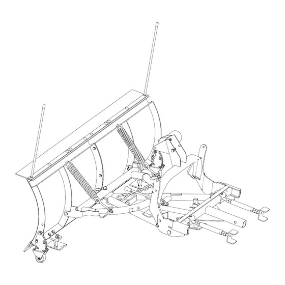
PARTS DESCRIPTION AND FUCTION 1.Main shovel group 2.Tension spring 9. Electric windlass 3.Plastic pipe 7. Slide Foot Weld Assembly 8. Suspension assembly 10. Right and Left- hand control screw weldings frame assembly 4. Cast iron wheel frame assembly 1. Main shovel group 6. -
Page 11: Products Specifications
PRODUCTS SPECIFICATIONS Snow Plows Attachment Model No TMG-TSP72 Overall width 74.7" Cutting width 72" Overall length 60.3" Overall height 49" Cutting height 23" Rated line pull 2000lbs(907kgs) Motor DV12 Permanent magnet 0.5KW/0.7hp Operating weight 291lbs(132kg) Matchable trailer hitch Fits ANY vehicle that has a 2’’ Class III front mount receiver Features: Fits most Pickup trucks and SUVs. -
Page 12: Unpacking & Assembly
UNPACKING & ASSEMBLY After unpacking, check the following components www.tmgindustrial.com www.tmgindustrial.com Toll Free:1-877-761-2819 Toll Free:1-877-761-2819 11/31... - Page 13 DESCRIPTION DESCRIPTION Strengthened cap head Right Main Shovel Weldment square neck bolts M10×25 Strengthened cap head Left Main Shovel Weldment square neck bolts M10×30 Rubber sheet Plain Washers Ø10 Pressure Plates 1 Hexagon Locknuts M10 Pressure Plate 2 Full Thread Hexagon Bolts M12×40 Plastic pipes Hexagon Locknuts M12 Short flat Knives...
- Page 14 1. Install the Main shovel group C10 C9 Installation steps: Connect the left main shovel weldment (C1) and the right main shovel weldment (C2) by means of M10×30 hexagonal head all- thread bolts C21), (C9) flat washers 10 (2PCS), and (C10 )M10 type 1 non-metallic insert hexagonal locknuts. Connect the pressure plate (C5) and Rubber sheet (C7) to the Main shovel group (C1+C2) by means of head square neck bolts (C15) , (C9) flat washers 10 (2PCS), and (C10 )M10 type 1 non-metallic insert hexagonal locknuts.
- Page 15 PART NO. DESCRIPTION PART NO. DESCRIPTION Left main shovel weldment Sliding foot weldment assembly Strengthened cap head Right main shovel weldment square neck bolts M10×25 Short flat knives Plain washers Ø12 1 Non-metallic insert Long flat knife hexagonal locknuts M12 Pressure Plates 1 Full-thread hexagon bolts M12×40 Pressure Plate 1...
- Page 16 2. Install the A-frame and D-frame Installation steps: Connect the D-frame weldment assembly (B2) and Tension spring (B17) ,by 1 Non-metallic insert hexagonal locknuts (C15), (C16) flat washers 10 (2PCS), and Hexagon Nuts(B16) Connect the A-frame weldment assembly(B1) and Strut weldment (B12) ,by R pin (B27) and pin (B26). Connect the A-frame weldment assembly(B1) and D-frame weldment assembly (B2) ,by Screened pipe(B11)),Hexagon head bolts(B5) and hexagonal locknut(B4), put one Plain washer (B3) front and one back importance: All bolts are locked in place without shaking.
- Page 17 3. Install the Suspension Weldment Assembly Installation steps: Connect the T-frame weldment assembly (A2) and hand control screw weldment (A11) ,by 1 Non-metallic insert hexagonal locknuts (A15) and Hexagon head bolts(A16) ,put one Plain washer (A14) front and one back Connect the T-frame weldment assembly (A2) and suspension weldment assembly(A1) ,by Connecting pins (A3) and R pin(A5) , lock plate( A4) Importance: All bolts are locked in place without shaking.
- Page 18 4.Final installation Installation steps: Connect the Electric windlass (D1) and the suspension weldment assembly (A1) ,by hexagonal locknuts (D3) and Full-thread hexagon bolts (D4) , put one Plain washer(D2) and one back. Connect the A-frame weldment assembly(B1) and the suspension weldment assembly (A1) ,by connection pin (A3) , M8×55 hexagon bolt (B31) and 1 Non-metallic insert hexagonal locknuts (B8) , put one Plain washer(B7) and one back, and both sides of the Square pin(B23) fixed.
- Page 19 PART NO. DESCRIPTION PART NO. DESCRIPTION Suspension weldment Square pin Connecting pins pins A-frame weldment Split pins 3.2×25 D-frame weldment Full-thread hexagon bolts M8×55 u-bolt Electric windlass Plain washers Ø8 Plain washers Ø8 1 Non-metallic insert 1 Non-metallic insert hexagonal hexagonal locknuts M8 locknuts M8 Tension springs...
-
Page 20: Matchable Trailer Hitch
MATCHABLE TRAILER HITCH Fits ANY vehicle that has a 2’’ Class III front mount receiver , below is a quick breakdown of the 3 matching hitch ratings, associated load carrying capacity and typical receiver sizes : Receiver Size Class III 3500-8000Ibs 300-800 Ibs 2’’... - Page 21 OPERATION WARNING! Always inspect Snow Plow components, connections, and fasteners for wear or damage every time you attach or detach the Snow Plow. Worn or damaged components may allow the Snow Plow to fail without warning, resulting in serious injury or vehicle damage. Before plowing the first time, be sure all fixtures, connections, and parts are tight and properly aligned.
- Page 22 TIPS AND TRICKS Staking – Before snow even begins to fall, use stakes or wands to mark the edges of places that need to be plowed, so that you can plow safely and neatly without damaging the surrounding lawns and gardens. You can also mark hydrants, utility boxes, gas meters, sewer vent pipes, etc.
-
Page 23: Operating Finish
OPERATING FINISH DETACHING THE SNOW PLOW Drive the vehicle to a clear area. 2. Raise the blade. 3. Lower the 2 fip-down castors and lower the rear support plate. Secure with pins. 4. Lower the blade. 5. Disconnect the electrical connections. 6. -
Page 24: Troubleshooting
TROUBLESHOOTING THE PLOW BLADE ROCKS OR TIPS FROM SIDE TO SIDE. It is normal for the whole assembly to rock back and forth when mounted on a vehicle, with the plow blade moving side to side from 20 to 25 cm (8 to 10 in.) This compensates for differences in terrain between what the plow rides on and what the vehicle is riding on. -
Page 25: Maintenance Schedule
MAINTENANCE SCHEDULE Using it in commercial applications or travelling above the recommended speeds will result in us voiding your warranty. It can also cause serious damage to the plow, or to your vehicle as well as possible personal injury. RECOMMENDS THE FOLLOWING GENERAL MAINTENANCE INFORMATION: Continuous heavy operation may demand a more intensive service regimen. -
Page 26: Exploded View & Parts List
EXPLODED VIEW & PARTS LIST 1. Snow Plow PART NO. DESCRIPTION PART NO. DESCRIPTION Suspension assembly Main shovel group Connecting frame assembly Motorized module 25/31 www.tmgindustrial.com Toll Free:1-877-761-2819... - Page 27 2. Suspension assembly PARTS LIST PART NO. DESCRIPTION PART NO. DESCRIPTION Right-hand adjusting screw Suspension weldment weldment T-frame weldment Adjusting tube weldment Connecting pins Left-hand control screw weldment Hexagon Nuts (levorotation) Lock plates Hexagon Nuts M18 R pins Ø5X130 Plain washers Ø12 Plain washers Ø8 1 Non-metallic insert 1 Non-metallic insert hexagonal...
- Page 28 3.Connecting frame assembly 27/31 www.tmgindustrial.com Toll Free:1-877-761-2819...
- Page 29 PARTS LIST PART NO. DESCRIPTION PART NO. DESCRIPTION A-frame weldment Tension springs D-frame weldment plug Plain washers Ø16 Compression spring 1 Non-metallic insert Spring-type straight pin hexagonal locknut M16 Hexagon head bolts M16×80 Handle bonding u-bolt Haft Plain washers Ø8 Square pin 1 Non-metallic insert Full-thread hexagon bolt M8×30...
- Page 30 4. Main shovel group www.tmgindustrial.com Toll Free:1-877-761-2819 29/31...
- Page 31 PARTS LIST PART NO. DESCRIPTION PART NO. DESCRIPTION 1 Non-metallic insert Left main shovel weldment hexagonal locknuts M12 Right main shovel weldment Full-thread hexagon bolts M12×40 Short flat knives Plain washers Ø16 Long flat knife Hexagon Nuts M16- Pressure Plates 1 Full-thread hexagon bolts M10×30 3 inch medium cast iron Pressure Plate 1...
- Page 32 5. Motorized module PARTS LIST PART NO. DESCRIPTION PART NO. DESCRIPTION 1 Non-metallic insert hexagonal Electric windlass locknuts M8 Plain washers Ø8 Full-thread hexagon bolts M8×30 Please refer to our website for detailed warranty conditions and coverage. WARRANTY INFOEMATION: For the most up-to-date and comprehensive warranty information, visit www.tmgindstrial.com www.tmgindustrial.com Toll Free:1-877-761-2819 31/31...
Need help?
Do you have a question about the TMG-TSP72 and is the answer not in the manual?
Questions and answers