Table of Contents
Advertisement
Quick Links
Advertisement
Table of Contents

Subscribe to Our Youtube Channel
Summary of Contents for BTECH S5
- Page 1 Installation Manual • Rockaway, NJ 07886, U.S.A. www.btechinc.com...
- Page 2 BTECH Inc. takes pride in the quality of its new documentation. However, technical inaccuracies, typographical errors and editorial omissions do occur from time to time. Although the documentation is provided “as is,” and BTECH Inc. disclaims all direct, indirect or consequential damages that may result from such errors, please let BTECH Inc. know immediately if you discover inaccuracies, errors or omissions.
-
Page 3: Table Of Contents
Table of Contents Product Overview ................5 *Product Warranty ................6 A. Hardware Warranty......................6 B. Software Warranty....................... 6 C. Entitlement During the Applicable Warranty Period ............6 Telephone Support ......................6 Firmware/Software for the Version Licensed............... 6 General ..........................8 Limitation of Liability ......................8 Getting Ready ...................9 Step 1: Check Shipped Materials.................... - Page 4 Step 10: Set up S5 Battery Validation System ..............54 Appendix..................55 *BVS S5 Startup & Training Form must be completed and returned to BTECH in order to initiate the Product Warranty. This record verifies that the system(s) has (have) been started up propertly. A blank copy of this form can be found in the Appendix of this manual.
-
Page 5: Product Overview
Product Overview PRODUCT OVERVIEW Thank you for choosing BTECH’s S5 Battery Monitoring and Validation System. The S5 is BTECH’s fifth generation of battery monitoring products, including all of the engineering and field experience the company has generated since its inception in 1989. Today, with over 3000 systems installed worldwide, BTECH is the undisputed leader in the battery monitoring industry with experience that is unmatched. -
Page 6: Product Warranty
BTECH, at its sole discretion, develops and releases said firmware patch, or upgrade, or software bug fix, BTECH may make it available to the End User at no charge. - Page 7 Hardware Products during the above referenced periods: a. BTECH must be notified by End User prior to the return of said Product. Within ten (10) days of the date of said notification BTECH will provide End User with a valid Return Material Authorization Number (RMA).
-
Page 8: General
Replacement Products or Licensed Materials outside the scope of this warranty or with respect to Product(s) or Licensed Materials out-of-warranty will be furnished at the established charges of BTECH then in effect. End User shall ensure that BTECH will have full and free access to the Products and Licensed Materials and End User’s site, if required. -
Page 9: Getting Ready
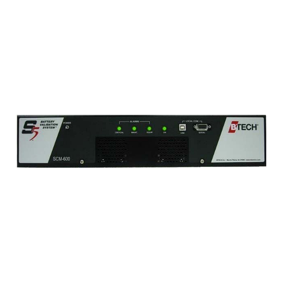
Getting Ready GETTING READY Step 1: Check Shipped Materials ......9 Step 2: Gather Tools..........14 Step 1: Check Shipped Materials Image sizes not shown to scale. Modules Part Name Picture Purpose Gathers data from the battery validation system; sends the SCM-600 (System Control Module) data to the BVM software installed on a PC Gathers up to 24 voltage... -
Page 10: Cables And Wires
Cables and Wires WARNING BTECH Inc. only sanctions the use of wiring/cables included in the shipment. Use of custom or third-party cables without the expressed written consent of BTECH can damage the system and void the warranty. Part Name/Description Picture... - Page 11 Senses ambient and pilot 600, 1 to 4 thermistor(s)) battery temperatures per VM- In place of IEC Power Cord. Used when powering S5 1 per S5, 48 Volt Conversion Kit directly from the batteries SCM-600 rather than an AC source. Installation Manual...
-
Page 12: Plugs And Connectors
4-position screw terminal (pair) SCM-600 the SCM-600 Attaches auxiliary outputs out 2 per 9-position screw terminal (pair) SCM-600 of the SCM-600 Attaches to SCM-600 Comm 2 per Communications Termination Plug plug and last module’s OUT SCM-600 Comm plug S5 Battery Validation System... -
Page 13: Brackets And Fasteners
Getting Ready Brackets and Fasteners Part Name Picture Purpose To attach VSL pigtail quick Stainless steel clamp (SS clamp) disconnect tabs to battery bars/ varies straps Thermistor installation kit (mounting To attach thermistors to 1 per clips and insulated tape) batteries, walls or racks thermistor VM-24/CM-2 right angle mounting... -
Page 14: Step 2: Gather Tools
Bushing, plastic (1” and 7/8”) cables that pass-through knock- SCM-600 outs. Step 2: Gather Tools Unless otherwise noted, these items are not provided by BTECH, Inc. Part Name Picture Purpose Lay on top of battery(s) to protect installer Rubber insulating blanket... - Page 15 The small “hook” tool is used to pry open wire hole by inserting it into the 16 and 10-pin WAGO plugs. WAGO connector tool set (provided by BTECH) Other pointed tools are pushed into the plugs to create an opening or used in screw terminals...
- Page 16 S5 Battery Validation System...
-
Page 17: Installation Procedure
S5 system (can be 1 or more cells/jars in a unit) battery cell battery jar: one to six cells enclosed in a common smallest... -
Page 18: Installation Overview/Example
The following is a simplified example showing where connectors and wiring go, and how battery cells and VSLs are numbered. For Overview/Example detailed instructions, read the Battery Wiring List in the Appendix and the step-by-step procedure starting on page 20. S5 Battery Validation System... -
Page 19: Installation Precautions
When working near battery cells, cover them with a rubber blanket WARNING BTECH Inc. strongly recommends that only persons trained in the techniques and procedures necessary to assure personal safety when working with the high-energy batteries perform installation of its S5 systems. -
Page 20: Step 1: Install Connectors
Extra-long bolts (if bolts on battery 1 for each do not have at least 3/8” connector (9.525mm) space free to double- 1 of either Lock or star washers (supplied) Lock washer Star washer 1 for each Flat washers (supplied) connector S5 Battery Validation System... - Page 21 ...plus, for connections on battery straps/bars: NOTE: If possible, it is best to attach connectors directly to the battery terminals Item Picture 1 for each Stainless steel clamps (SS clamps) connector Anti-corrosive grease (e.g. No-Ox) 1/8” Insulated allen wrench S5 Battery Validation System...
-
Page 22: Procedure
7. Drawing of numbered tapes being stuck on batteries 2. Determine where connectors go (see Cable Work Sheet & Battery Wiring List) VM-24 Module 1 Wire color: Yellow VM-24 Module 1 Leng VSL No. Jar # Terminal # S5 Battery Validation System... - Page 23 Installation Procedure 3. Protect yourself from 4a, Install 1/4” male quick disconnect tabs on battery post, OR shock 2. Rubber mat over battery cells 4b. Install 1/4” male quick disconnect tabs on threaded insert, OR 4c. Install 1/4” male quick disconnect tabs on a battery strap 11.
-
Page 24: Step 2: Mount System Modules
SCM-600 Rack Mounting 1 pair per Brackets and SCM-600 SCM-600 Mounting Hardware Kit if mounting within a rack SCM-600 Bottom Mounting 1 pair per Rails and SCM-600 Mounting SCM-600 Hardware Kit if mounting to a flat surface S5 Battery Validation System... - Page 25 Installation Procedure Procedure 1. See where to place the SCM-600 (see Battery Map) See S5 SCM-600 Cabinet / Wall Mounting Configuration or S5 SCM- 600 Rack Mounting Configuration in Appendix. 15. Drawing of clearance for cables needed behind SCM in rack 2.
- Page 26 4. Install SCM-600 mounting brackets / rails 5. Mount the SCM-600 in place Rack Mounting Brackets Bottom Mounting Rails S5 Battery Validation System...
-
Page 27: Mount Vm-24 (Voltage Module)
Installation Procedure Mount VM-24 (Voltage Module) Items Needed Item Picture VM-24 Varies Battery Map See Appendix #2 Phillips-head screwdriver Rubber insulating mat Brackets and other hardware for mounting (provided) Mounting brackets (pair) Stacking brackets (pair) varies Universal mounting bracket Installation Manual... - Page 28 5. Mount the VM-24 as shown in the Battery Map USE ANY MOUNTING Attach the module with mounting brackets. METHOD Stack modules together with Use the holes in the stacking brackets. universal mounting bracket for tie- wraps or screws. S5 Battery Validation System...
-
Page 29: Mount Cm-2 (Current Module)
Installation Procedure Mount CM-2 (Current Module) Items Needed Item Picture CM-2 Battery Map See Appendix #2 Phillips-head screwdriver Rubber insulating mat Brackets and other hardware for mounting (provided) Mounting brackets (pair) Stacking brackets (pair) varies Universal mounting bracket Installation Manual... - Page 30 5. Mount the CM-2 as shown in the Battery Map USE ANY MOUNTING Attach the module with mounting brackets. METHOD Stack modules together with Use the holes in the stacking brackets. universal mounting bracket for tie- wraps or screws. S5 Battery Validation System...
-
Page 31: Step 3: Run Wires And Attach Connectors To Them
Installation Procedure Step 3: Run Wires and Attach Connectors to Them Run Wires from VM-24 to Battery Jars Items Needed Item Picture Battery Wiring List See Appendix Battery Map See Appendix varies - see VSL pigtails Wiring List VSL wires with 1/2 fuse varies - see holders attached (lenghts Wiring List... - Page 32 Wire cutter Rubber insulating mat Tie wraps required S5 Battery Validation System...
- Page 33 Installation Procedure Procedure 1. Attach the VSL Pigtails to the Battery Jars b. Attach the appropriate VSL pigtails to the 1/4” male quick a. Protect yourself from electrical shock disconnect tabs. See Cable Work Sheet. 31. Picture of plugging a VSL pigtail to a quick disconnect tab 2.
- Page 34 For your installation, see the wire list in the Appendix of this book. b. Use WAGO connector ‘hook’ open pin hole & insert wire c. Insert all the wires as directed S5 Battery Validation System...
- Page 35 Installation Procedure d. Insert the WAGO plugs into the VM24 Installation Manual...
-
Page 36: Daisy-Chain Vm-24S And Cm-2S To Scm
18-gauge wires (both orange) 1 per SCM- 600, 2 per 4-pin white WAGO plug VM-24, 2 per CM-2 1 per SCM- 600, 2 per 2-pin orange WAGO plug VM-24, 2 per CM-2 Communications Termination 2 per SCM- Plug S5 Battery Validation System... - Page 37 Installation Procedure 1 per WAGO connector tool for 4- SCM-600 pin WAGO plug 1 per WAGO connector tool (3/32” SCM-600 flat-headed screwdriver) Wire cutter/stripper Rubber insulating mat Installation Manual...
- Page 38 SCM must be cut before the module as shown in the second picture below. Do not terminate that green wire into that “IN” white COMM plug. Green communications wire WILL be terminated into EVERY OTHER white COMM plug. Repeat steps 2-4 for each cable. S5 Battery Validation System...
- Page 39 Installation Procedure 7. Attach two cables to the next unit, one for “in” and one for “out.” Repeat for all units except the last unit. Repeat steps 2-4 for each cable. To next unit From previous unit 8. At the last unit, attach an “in” cable and plug the second Communications Termination Plug into the OUT COMM plug of the final module.
-
Page 40: Install Cts (Current Transducers)
Install CTs (Current Transducers) Items Needed Item Picture CT (current transducer) 1 per CM-2 (provided) Rubber insulating mat Wire cutter/stripper WAGO connector tool (3/32” flathead screwdriver) S5 Battery Validation System... - Page 41 Installation Procedure Procedure NOTE: CT and CM-2 come as calibrated pairs. BE SURE SERIAL NUMBERS MATCH WHEN INSTALLING. Also, install the CT in a location that is readily accessable (accessable easily and safely, even when batteries are on charge). 2. Unclip the CT to separate in half. Place the CT around 3.
-
Page 42: Install Lcl Wires
1/2 fuse holder attached; lead color as required by string LCL pigtail with fuse holder varies attached (provided) varies In-line taps 1/2” or 5/8” high-voltage insulated wrench (for small or large tap) Wire cutter/stripper Rubber insulating mat Tie wraps required S5 Battery Validation System... - Page 43 Installation Procedure Procedure Step 1: Attach LCL pigtails to battery a. Protect yourself and equipment b. See where LCL cables go Cable Work Sheet for S5 Battery Validation System NOTE: The Battery Model S5 Quantity: Wiring List and FOR: Battery Map...
- Page 44 If tap is provided, attach it to charging cable in center of string pigtail------ battery cable Step 2: Attach LCL cable to fuse holder b. Connect LCL cable at fuse holders; do NOT insert fuse a. Protect yourself and equipment at this time. 2. Rubber mat over cells S5 Battery Validation System...
- Page 45 Installation Procedure Step 3: Route LCL cables to SCM-600 a. Protect yourself and equipment See picture in Step 1a regarding the proper routing of LCL’s relative to VSL’s 2. Rubber mat over cells b. Leave 1 foot of service c. Make LCL wires perpendicular to VSL wires, or at least 2 d.
-
Page 46: Install Thermistors (Temperature Monitors)
Ambient thermistor w/cable varies Battery thermistors w/ cable 1 per Thermistor mounting kit thermistor 1 per VM- 8-pin screw terminal 1 per 2-pin screw terminal SCM-600 (provided) WAGO connector tool (3/32” flat head screwdriver) Duct tape (not provided) S5 Battery Validation System... - Page 47 Installation Procedure Installing Battery Thermistors 1. See where thermistors go BTECH Battery Wiring List Model: Job # : Battery Mfg & model: S/N: FOR: NOTE: The Battery Wiring List TAG: Battery: and Battery Map shown NOTE: See Drawing XXXX for location and mounting of VM-24 modu are examples only.
- Page 48 Installing the Ambient Thermistor 1. Prepare thermistor wires 2. Insert into screw terminal 4. Mount near battery 3. Plug into SCM-600 S5 Battery Validation System...
-
Page 49: Step 4: Ground Scm-600
Installation Procedure Step 4: Ground SCM-600 WARNING! Failure to propertly ground SCM-600 can lead to electrocution, damage to Battery Monitoring System, and/ or incorrect measurments of batteries! Items Needed Item Picture approx 10 Stranded ground wire (10 feet AWG) with 3/8” ring lug Flat-headed short-handled screwdriver (not provided) -
Page 50: Step 5: Add Operating Power
1. Attach power cord to SCM-600 2. Plug into wall or UPS power supply OR, use optional S5, 48 Volt Conversion Kit to power S5 from batteries, if appropriate... 1. Connect stainless steel clamps to bus bars. Red/white 2. Terminate opposite end of cables into 2-pin green plug. -
Page 51: Step 6: Install Fuses
Installation Procedure Step 6: Install Fuses Items Needed Item Picture varies (1 per VSL VSL Fuse plus spares) varies (1 per LCL LCL Fuse plus spares) Procedure 1. Take apart VSL fuse 2. Insert fuse 3. Put fuse holder together 4. -
Page 52: Step 7: Connect To Computer
1 per DB-9 Serial Communications SCM-600 Cable (6 foot) USB Communications Cable Procedure 1. Attach cable to SCM-600 2. Attach cable to computer Step 8: External Input Connections 4-pin plugs and auxiliary 1 pair input wire S5 Battery Validation System... -
Page 53: Step 9: Alarm Relay Contacts
Installation Procedure 4-pin plug (connector) as viewed from the rear of the SCM-600 INPUT #1 = 1(Hi) 2(GnD) INPUT #2 = 3(Hi) 4(Gnd) INPUT #3 = 5(Hi) 6(Gnd) INPUT #4 = 7(Hi) 8(Gnd) Step 9: Alarm Relay Contacts 9-pin plugs and auxiliary 1 pair output wire 9-pin plug (connector) as viewed from the rear of the SCM-600... - Page 54 ALARM #5 = 13-15 CLOSURE = ALARM; 13-14 OPEN = ALARM ALARM #6 = 16-18 CLOSURE = ALARM; 16-17 OPEN = ALARM Step 10: Set up S5 Refer to S5 Battery Validation Manager Software & Battery Validation System Battery Validation Operating Manual System Battery Validation Manager Software &...
- Page 55 This record verifies that the system has been started up propertly. This form should be completed and returned for each S5 system that is installed. A blank copy of this form can be found in this Appendix and in the Appendix of each S5’s Installation Manual.
- Page 56 • S5 Battery Validation System...
- Page 57 S5 Battery Validation System...
- Page 58 S5 Battery Validation System...
- Page 59 Appendix Installation Manual...
- Page 60 ) wire clipped? Section B. Operation Verification 1. After completing Section A, power can be applied to the S5 BVS and turn on both switches. 2. Confirm that the number of modules matches the configuration of the setfile. 3. Measure & record the voltage supplied to the last module ____________ (Min acceptable is 18 VDC) 4.
- Page 61 4. Download data from controller saved in the customer’s PC data directory 5. Is the set file, as currently loaded into the S5 Controller, saved in the customer’s data directory? 6. Was a custom Battery Map prepared (standard is to complete this onsite)? 7.
- Page 62 Items that need to be shipped to customer: ITEM COST DATE SHIPPED Items to be sent back from customer: ITEM DATE RECEIVED Contacts: Name: Address: Phone # Fax # Email F 7.5.2-3 BVS S5 Start-up & Training Rev 2 8/10/06...
- Page 63 15 VM24 ______ ______ ______ ______ 16 VM24 ______ ______ ______ ______ 17 VM24 ______ ______ ______ ______ 18 VM24 ______ ______ ______ ______ 19 VM24 ______ ______ ______ ______ 20 VM24 ______ ______ ______ ______ F 7.5.2-3 BVS S5 Start-up & Training Rev 2 8/10/06...
Need help?
Do you have a question about the S5 and is the answer not in the manual?
Questions and answers