Advertisement
Advertisement
Table of Contents

Subscribe to Our Youtube Channel
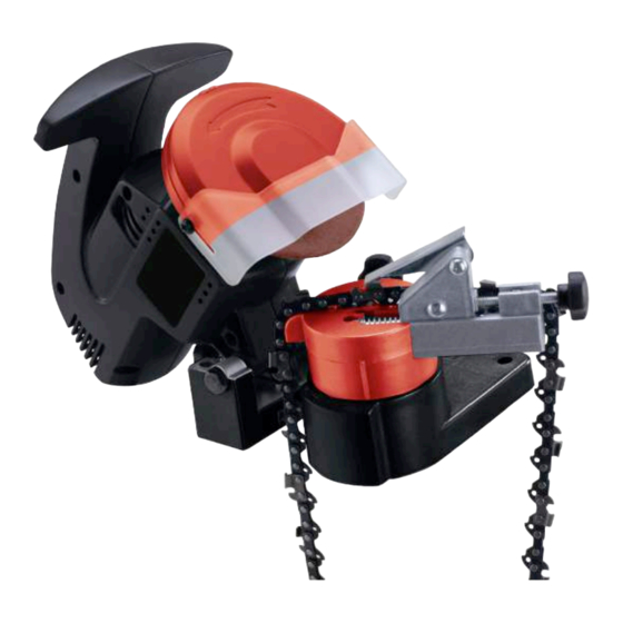
Summary of Contents for Greencut SH0905
- Page 1 ASSEMBLY AND OPERATING INSTRUCTIONS...
-
Page 2: Specifications
Specifications Motor 230V,50Hz, rated: 220W, Max : 320W @ 50% Duty Cycle R/min 7500rpm Table/Vise Angles 35 Degrees Right to Left Arbor Diameter 10mm Wheel Dimensions 100mm Dia. X 3.2mm Thick Overall Dimensions 175mmW x 320mmL x 210mmH Weight 1.60kgs Save this manual You will need the manual for the safety warnings and precautions, assembly instructions, operating and maintenance procedures, parts list and diagram. - Page 3 Page 2 9. Maintain tools with care. Keep tools sharp and clean for better and safer performance. Follow instructions for lubricating and changing accessories. Inspect tool cords periodically and if damaged, have them repaired by an authorized technician. The handles must be kept clean, dry, and free from oil and grease at all times. 10.
-
Page 4: Additional Safety Warnings
Page 3 Additional Safety Warnings Grinding Wheel Warnings 1. Do not use a grinding wheel if it is chipped, cracked, or worn. You can check if the wheel has cracks not visible to the human eye by hanging it up by the central hole and tapping it with a non-metal object (ie: screwdriver handle). -
Page 5: Operation
Page 4 Warning! Always unplug the unit before changing grinding wheels, or when making any adjustments to the Sharpener. Mounting a Grinding Wheel Refer to the assembly drawing on page 10 and FIGURE 3 and FIGURE 4 below. Raise the Engine Casing(#12+24) and lock it in the up position by tightening the Screw (# 45) Remove the two screws holding the Grinding Wheel Cover (#2), Set the cover aside. - Page 6 Page 5 Operation (continued) 2. Lift up the Chain Stop (#53) and secure the chain in the Fixed Disk (#50). See FIGURE 6. 3. Lower the Chain Stop (#53) so that it is positioned on the tooth (blade) you want to start with. See FIGURE 5. Tip of Chain Stop positioned against tooth.
- Page 7 Page 6 Operation (continued) 8. Lock the chain in the Fixed Disk FIGURE 8 (#50) by turning the Screw (#52). See FIGURE 8.The Screw (#52) should be situated so that you can easily release and tighten it . You will need to release it Sharpening.
-
Page 8: Maintenance
Page 7 Operation (continued) 5. After you finish sharpening all of the teeth on the chain, turn off the machine by pushing the red button on the Switch (#25) and unplug the unit. 6. Loosen the Lock Wheel (#46) and reset the angle so that the first tooth that hasn’t been sharpened is FIGURE 11 positioned against the Screw (#53) and locked in as... - Page 9 Page 8 Parts List Part# Description Part# Description Safe Guard Bolt Grinding Wheel Cover Clip Screw Pressure Plate Left Cover Grinding Wheel Flat Pad Output Shaft Screw Bearing Screw Shaft Circlip Handspike Synchronous Belt Spring Screw Big Belt Wheel Base Left Engine Casing Bolt Flat Pad...
-
Page 10: Assembly Drawing
Page 9 Assembly Drawing...


Need help?
Do you have a question about the SH0905 and is the answer not in the manual?
Questions and answers