
Related Manuals for MONARCH INSTRUMENT F2A1X

Summary of Contents for MONARCH INSTRUMENT F2A1X
- Page 1 Instruction Manual F2A1X Frequency to Analog Converter Module 15 Columbia Drive • Amherst, NH 03031 USA Phone: (603) 883-3390 • Fax: (603) 886-3300 E-mail: support@monarchinstrument.com Website: www.monarchinstrument.com...
- Page 2 SAFEGUARDS AND PRECAUTIONS Read and follow all instructions in this manual carefully, and retain this manual for future reference. Do not use this instrument in any manner inconsistent with these operating instructions or under any conditions that exceed the environmental specifications stated.
-
Page 3: Table Of Contents
5.0 SPECIFICATIONS ............... 7 5.1 Compliance ..............7 6.0 SENSORS AND ACCESSORIES ........... 8 7.0 APPENDIX A - SERIAL PROGRAMMING COMMANDS ... 10 Monarch Instrument’s Limited Warranty applies. www.monarchinstrument.com for details. Warranty Registration and Extended Warranty Coverage information is available... -
Page 4: Overview
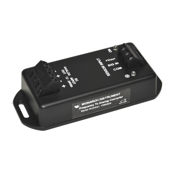
(measuring RPM for example) or any source of digital signal not exceeding 12 volts. The F2A1X requires 12-24 V dc input power and consumes less than 100 mA. It can be operated freestanding or can be mounted to a panel using the fixed wings on either end of the device. -
Page 5: Power
– terminal. 2.2 Analog Output The F2A1X Frequency to Analog Converter Module may be equipped with either a Voltage Output (0-5 V dc) or a Current Output (4-20 mA) depending on how the unit was ordered. Connections are made to the half of the 4-way terminal block marked Analog Out. -
Page 6: Voltage Output Option
2.2.1 Voltage Output Option The voltage output is 0 to 5 V dc. Connections for voltage out are made to the terminals marked ANALOG OUT. Connect the positive side of the load to the terminal marked + and the negative or common side of the load to the terminal marked –. - Page 7 Typical input impedance is 10 Kohms. Common or Negative connection for both signal and power from most sensors/sources. Refer to Sections for input option settings. Typical connection for Monarch Instrument standard sensors is shown below: Figure 2 Sensor Connection Detail...
-
Page 8: User Selectable Hardware Settings
Figure 3 AC Source Connection Detail 3.0 USER SELECTABLE HARDWARE SETTINGS There are several settings relating to the sensor input that can be set by the user. The settings are done by moving jumpers on the circuit board inside the housing. -
Page 9: Sensor Power Voltage
DC (factory default) for most digital sources or AC for sine wave and bidirectional sources or sensors that provide negative going pulses. 4.0 USER PROGRAMMABLE SOFTWARE SETTINGS All the programmable settings of the F2A1X Frequency to Analog Converter Module can be set by using the optional USB Programming Cable and downloadable PM Remote PC Software. -
Page 10: Specifications
5.0 SPECIFICATIONS Specifications* F2A1X Frequency to Analog Converter Module Input Range 0.1 to 10 KHz, 5 to 600,000 RPM Accuracy 0.02% FS † 0 to 5 V dc out, 5 mA 15-bit resolution; Voltage Output zero and full scale settings as specified when ordered or... -
Page 11: Sensors And Accessories
6.0 SENSORS AND ACCESSORIES For a complete list of accessories, see webpage. Sensors: PN: 6180-056 Remote optical LED sensor with tinned Remote Optical wire termination, 3-wire connection ROLS PN: 6180-030 Remote optical laser sensor with 8 ft. Remote Optical cable, 3 tinned leads Laser PN: 6180-080 Rugged laser sensor with removable 3... - Page 12 Accessories: USB Programming PN: 6180-031 Enables the user to connect the F2A1X Cable to a Windows® PC USB port to use PM Remote Software to program the unit. The software also allows remote monitoring of the RPM using a graphic display or an Excel™...
-
Page 13: Appendix A - Serial Programming Commands
7.0 APPENDIX A - SERIAL PROGRAMMING COMMANDS Programming the unit requires the optional USB Programming Cable with associated PM Remote software and a PC running Windows XP or later with an available USB port. All serial commands are @ then two or more characters or words separated by a delimiter “/”. - Page 14 @CH_A/LOEND = 12 Sets low end time; allows a minimum (or 1_SEC, HALF) reading of 5 RPM, 60 RPM, or 120 RPM @CH_A/GATE Show Gate Speed (default is 12) @CH_A/GATE = STD Sets Gate Speed (default is 1/100) (1/100 Second) or FAST (1/1000 second) @DECPT Shows the number of decimal places...
- Page 15 This page intentionally left blank.
- Page 16 Measure ● Monitor ● Maintain Monarch Instrument is committed to excellence and quality in manufacturing, sales, and service. ™ Track-It Data Loggers Panel Tachometers Portable Tachometers Frequency Portable Strobes Fixed Mounted Converters Strobes ™ Speed Sensors DataChart Paperless Recorders 15 Columbia Drive, Amherst NH 03031 USA Tel.: (603) 883-3390 // 800-999-3390...
Need help?
Do you have a question about the F2A1X and is the answer not in the manual?
Questions and answers