
Summary of Contents for Sonodyne SyNC 1001
- Page 1 SyNC 1001 IP enabled Digital Conference System Controller Installation & Operating Manual www.sonodyne.com...
- Page 2 SyNC 1001...
-
Page 3: Table Of Contents
3.3 Connection with camera ............CHAPTER 4: WORKING ENVIRONMENT AND MAINTENANCE ......4.1 Public areas ............... 4.2 Technical rooms ..............4.3 System operator room ............CHAPTER 5: TECHNICAL SPECIFICATIONS ............. 28~29 5.1 System specifications ............5.2 Conference System Controller ..........SyNC 1001... -
Page 4: Chapter 1: Introduction
SPK:01 VOL:18 ID:002 SPK:01 VOL:18 ID:002 SPK:01 VOL:18 ID:002 SPK:01 VOL:18 ID:002 SPK:01 VOL:18 ID:002 SPK:01 VOL:18 ID:002 Delegate Delegate Delegate Delegate Delegate Delegate 2024-01-01 00:00:24 2024-01-01 00:00:24 2024-01-01 00:00:24 2024-01-01 00:00:24 2024-01-01 00:00:24 2024-01-01 00:00:24 SyNC 1001 • page 1... -
Page 5: System Technology
20Hz ~ 20kHz. The system is composed of controller unit, conference unit and application software. Among them, the conference unit has a chairman unit and a delegate unit, and the application software is composed of multiple application software modules. SyNC 1001 • page 2... -
Page 6: Application Software
“Speak Number” ◊ “APPLY”: When the delegate presses the microphone ON/OFF button to request to speak, the chairman unit can approve or reject his/her request. ◊ “VOICE”: The delegate's microphone is activated when spoken into. SyNC 1001 • page 3... - Page 7 7. Seamless connection with conference sign-in system and central control system The conference system is seamlessly connected with most Intelligent central control systems, thus forming a complete conference system solution. 8. Effective RFI (radio frequency interference) supression such as from mobile phones SyNC 1001 • page 4...
-
Page 8: Unpacking, In The Box, Mounting
3. 10m long cable with 8 pin DIN connector 4. Operating manual 1.5 MOUNTING The unit is designed for rack-mounting. It occupies 2RU rack space. Details of rack mounting are given under Section 5.2.1.1, on page 29 SyNC 1001 • page 5... -
Page 9: Chapter 2: Conference System Controller
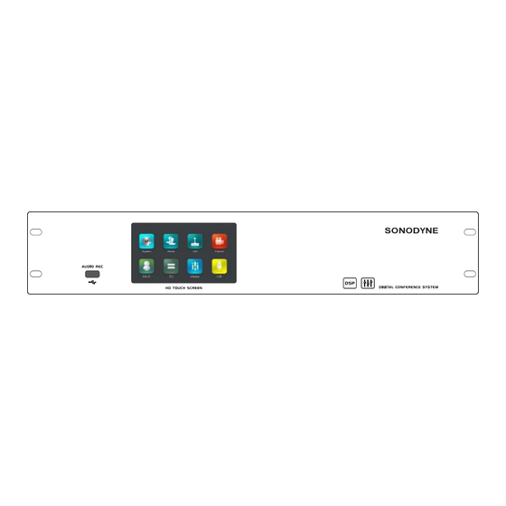
USB RECORDING OUTPUT PORT: Connect a USB flash drive or external hard disk to this socket for recording audio. The file format is WMA HD 5" TOUCH SCREEN: This is an interactive display cum touch screen. Details in Chapter 2 SyNC 1001 • page 6... - Page 10 DELEGATES – 8 PIN DIN: These are dedicated 8 pin sockets which can be used instead of the RJ- 45 interface. There are 4 such groups. The advantage of this interface is that it can carry a higher current since the conference controller supplies power to the conference units. However, the cable SyNC 1001 • page 7...
- Page 11 LINE OUTPUT: This comprises a pair of balanced and unbalanced line outputs. UNBALANCED LINE INPUT: This is an unbalanced line input for playing background music when the conference units are not in use. If any conference unit is spoken into, the background music stops. SyNC 1001 • page 8...
-
Page 12: Installation
The conference system controller has four groups of 8P-DIN conference unit output interfaces. You can connect the Sonodyne SyNC 3001 and SyNC 3002 to these sockets through standard 8 pin cables supplied with the conference units. There are also 3 groups of 6 RJ45 microphone unit interfaces for connecting conference units equipped with RJ-45 interface. - Page 13 The system controller has different types of output and input – both balanced and unbalanced, via different type of interfaces – Phoenix connector, RCA and 6.3 mm phone jack that allows it to be connected to different auxiliary equipment. SyNC 1001 • page 10...
-
Page 14: Setting & Operation
After completing the system installation and connection, you need to set up the conference system controller before the conference starts. The controller menu structure is shown in the figure below: FIG. 2.5: MENU OF CONTROLLER SyNC 1001 • page 11... - Page 15 After connecting, press the power switch and the controller will enter the boot screen, as shown in Fig 2.6.1 FIG. 2.6.1 After 2 seconds, it will automatically enter the standby mode. Swipe the screen to enter the main interface, as shown in Fig. 2.6.2 FIG. 2.6.2 SyNC 1001 • page 12...
- Page 16 After the editing is over, the current ID of all connected units will be displayed. You need to edit the ID once only. ID number is automatically saved in the unit. Once editing is over, press STOP to save and exit. SyNC 1001 • page 13...
- Page 17 Through the host name, the process of finally obtaining the IP address corresponding to the host name is called domain name resolution. "Network Status": Displays the current connection status between the device and the network SyNC 1001 • page 14...
- Page 18 Fig 2.6.6 FIG. 2.6.6 4. FACTORY RESET If the system cannot be used normally due to some problem, the data can be cleared by restoring the factory settings, as shown in Fig. 2.6.7 FIG. 2.6.7 SyNC 1001 • page 15...
- Page 19 • "Auto Time" :Any value between"0-999" seconds can be set. After the set time, if the microphone is not spoken into, it will automatically turn off SyNC 1001 • page 16...
- Page 20 "Lock Unit EQ": Press this key to lock the balance setting of the speaking unit microphone. "Reset Unit EQ": Press this key to restore the balance of the speaking unit microphone to the default setting. SyNC 1001 • page 17...
- Page 21 128. As long as the preset position of the whole project does not exceed 128, this value does not need to be modified. "Camera Speed": This sets the rotation speed of the camera. The default value is 100 SyNC 1001 • page 18...
- Page 22 ID will flash. Repeat the above procedure. Do this for all the speaking units that require camera tracking. d. After the camera setting is completed, the Camera Mode has to be set in “Call position” for normal operation SyNC 1001 • page 19...
- Page 23 If there is a speaking unit applying for service, this interface will pop up and prompt the service requirements of the applying unit, as shown in Fig. 2.7.8 FIG. 2.7.8 If the requested unit cancels the service, the above request will automatically disappear SyNC 1001 • page 20...
- Page 24 Click the Q value edit box to modify the Q value parameter, the unit is Q. d. Click the corresponding bypass button on the right to bypass the parameter setting of the corresponding segment. SyNC 1001 • page 21...
- Page 25 Click the "START" button in the USB recording menu, and the original red stop button will turn into a recording state icon c. After the meeting is over, press the "STOP" button to stop recording. The system will automatically save the recording file on the U disk. The audio file format is WMA SyNC 1001 • page 22...
-
Page 26: Chapter 3: System Connection
The socket in the T-junction is an 8 pin DIN socket. It is used to connect to the longer cable of the second T-junction cable for the unit after this. SyNC 1001 • page 23... -
Page 27: Extension Cable Of Conference Unit
The number of speaking units that can be connected to the output between the controller and the port of each unit of the controller first conference unit connected to 8-PIN interface-numbers of RJ45 interface-number of the socket conference speaking units conference speaking units 100m SyNC 1001 • page 24... -
Page 28: Connection Between The Controller And The Conference Unit
CHAPTER 3: SYSTEM CONNECTION CONNECTION BETWEEN THE CONTROLLER AND THE CONFERENCE UNIT FIG. 3.2 SyNC 1001 • page 25... -
Page 29: Connection With Camera
CHAPTER 3: SYSTEM CONNECTION CONNECTION WITH CAMERA FIG. 3.3 FIG. 3.4: COMMUNICATION CONNECTION BETWEEN THE CONTROLLER AND THE CAMERA CONNECTION METHOD DRAWING SyNC 1001 • page 26... -
Page 30: Chapter 4: Working Environment And Maintenance
By means of a microphone system, the operator should also be connected to a public - address system to remind the participants of operations, such as voting, signing-in, etc. longer end to the T- junction of the second unit. This enables cascading of multiple units. SyNC 1001 • page 27... -
Page 31: Chapter 5: Technical Specifications
EMC IMMUNITY Compliant with EN 55024 EMC APPROVALS CE, FCC POWER HARMONIC Compliant with EN 61000-3-2 VOLTAGE FLUCTUATIONS AND FLICKER Compliant with EN 61000-3-3 NOTE: Due to continuous improvements, all specifications are subject to change SyNC 1001 • page 28... -
Page 32: Conference System Controller
2P connector (unbal) x 1 (alarm device) AUDIO OUTPUT 3P connector( bal) x1, 3P connector (unbal) x 1 XLR (bal) x 1, 6.35mm (unbal) x 1, RCA (unbal) x 3 NOTE: Due to continuous improvements, all specifications are subject to change SyNC 1001 • page 29... - Page 33 NOTES SyNC 1001...
- Page 34 NOTES SyNC 1001...
- Page 35 NOTES SyNC 1001...
- Page 36 If you have anything less than a 5 star experience, please contact us at response@sonodyne.com and we will make it right SONODYNE, India • H.O.: 98 NB Block E New Alipore, Kolkata 700053 sonodyneofficial +91 9830855260 sonodyneofficial 1 800 31 31 035 response@sonodyne.com...
Need help?
Do you have a question about the SyNC 1001 and is the answer not in the manual?
Questions and answers