
Subscribe to Our Youtube Channel
Summary of Contents for CONCORD HANDILIFT
- Page 1 HANDILIFT Vertical Wheelchair Platform Lift INSTALLATION and SERVICE MANUAL (To Be Retained by Authorized Concord Dealer) © Concord Elevator Inc. Part # 000531 (Rev. 11/02)
- Page 2 IMPORTANT The Concord Handilift Vertical Wheelchair Platform Lift should be installed, maintained and serviced by authorized CONCORD ELEVATOR dealers only. The authorized CONCORD ELEVATOR dealer should refer to this manual for installation, maintenance, servicing and repairs. The owner is responsible for ensuring the ongoing safe operating condition of the Platform Lift through proper maintenance and servicing.
-
Page 3: Table Of Contents
TOWER ATTACHMENT (FOR NON FREE-STANDING UNITS ONLY) ........11 CAB ASSEMBLY ........................... 14 UNDER PLATFORM SAFETY PROP (OPTIONAL)..............17 AUTOMATIC RAMP (OPTIONAL)....................18 PORTABLE HANDILIFT UNIT (OPTIONAL) ................. 20 LIMIT SWITCH ASSEMBLY ......................21 TEST RUN THE LIFT ........................21 FINAL MECHANICAL INSTALLATION .................. 23 INSTALLATION OF CALL/SEND STATIONS (OPTIONAL)............ - Page 4 BEFORE LEAVING THE JOB SITE..................46 APPENDIX ‘A’ ......................... 47 ELECTRICAL SCHEMATICS ......................47 APPENDIX ‘B’ ......................... 63 ILLUSTRATED PARTS LIST......................63 MAIN DRIVE TOWER ASSEMBLY ....................64 MOTOR MOUNT SUBASSEMBLY ....................65 MOTOR MOUNT SUBASSEMBLY ....................66 FINAL TOWER ASSEMBLY (NO CAB)..................68 MAIN DRIVE NUT SUBASSEMBLY....................
-
Page 5: Year Limited Warranty
This warranty does not cover labor charges incurred in the removal, repair or replacement of parts. It is understood that labor charges may be covered for a certain period of time by the installing Concord dealer and; therefore, becomes the sole responsibility of such dealer. -
Page 6: Introduction
INTRODUCTION This manual contains installation and service in structions for the CONCORD HANDILIFT VERTICAL WHEELCHAIR PLATFOR M LIFT. We have spent much time and effort ens uring these instructions provide for a safe and efficient installation. Please follow these instructions exactly and call us mmediately if you have a problems or need assistance. -
Page 7: General Specifications
GENERAL SPECIFICATIONS CONCORD HANDILIFT PLATFORM LIFT Load Capacity 550 lbs. (250 kg) Optional Load Capacity 750 lbs. (341 kg) load capacity is available. This option requires a 20 ampere circ uit breaker and a minimum 10 gauge wire feed. The unit is built with a 20 am pere overload. -
Page 8: Tools And Materials Required
TOOLS and MATERIALS REQUIRED Standard Mechanics Tools to Include: • Set of Mechanical Sockets and Wrenches (1/4" - 1 1/4" Imperial Sizes) • Adjustable Wrench (Minimum 10") • Screwdrivers (Slotted and Phillips) • 4'-0" Carpenter’s Level and Square • Allen Wrenches (Keys) (1/8" - 3/8" Imperial) •... -
Page 9: Installation Safety Tips
10) Never place yourself in a position where you may be harmed (i.e., between shear point under heavy objects, in the path of moving parts, etc.). Always remember and practice, SAFETY FIRST . IT IS RECOMMENDED YOU READ AND FULLY UNDERSTAND T HIS MANUAL BEFORE BEGINNING THE INSTALLAT ION OF THE HANDILIFT. -
Page 10: Preliminary Installation Procedures
CONCORD DEALER should check for freight damage. Claims for any age must be made to the carrier and Concord immediately. If there is visible damage to the unit upon delivery, do not accept the shipment without recording such damage on the Shipping/Receiving Documents. -
Page 11: Verify The Handing Of The Unit
D. VERIFY THE HANDING OF THE UNIT The “handing” of the Handilift is determined by standing at the bottom landing facing the lift. See Figure # 1. The tower will be positioned either on the “right” or the “left”. If the tower is on the “left”... -
Page 12: Preparation For Positioning
E. PREPARATION FOR POSITIONING The Concord Handilift unit must be moved utilizing a dolly, cart or other wheeled means. NEVER d rag the Handilift into position. Dragging the unit may cause damage to the components and/or the cu stomers’ premises. -
Page 13: Installation Procedures
INSTALLATION PROCEDURES HOISTING A dolly, a cart or a hoist is highly recommended to raise or lower the Handilift over short distances. Make sure that you have enough manpower available during the site placement part of the installation. Use extreme care and ensure that no one is under the unit or in any place where they may be struck by any part of the equipment. -
Page 14: Anchoring
1/2" (13 mm) minimum diameter and 2-1/2" (64 mm) minimum length. sure that the Handilift is level, plumb and square before, during and after you have completed the anchoring procedure. “Drop” a plumb line along each of the two rails and make sure that the rails a plum b in both directions. -
Page 15: Tower Attachment (For Non Free-Standing Units Only)
OWER ATTACHMENT (FOR NON FREE-STANDING UNITS ONLY) he tower must be fastened to a structurally stable wall with a maximum center size of 24" (610 mm) nd with the tower tie brackets provided within the tower. (This depends on the model and the travel eight). - Page 16 Figure # 4 Footprint Drawing Non Free-Standing...
- Page 17 Figure # 5 Position of Tower Tie Brackets...
-
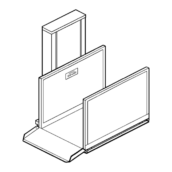
Page 18: Cab Assembly
CAB ASSEMBLY Install the main power supply. See section Appendix 'A' - Electrical Schematics, Sheet 7.0. Before the platform is installed, it is easy to access all parts of the oil reservoir and lifting bracket. Check that no damage has occurred during shipping or installation. Check that the split nut switch operates well and check that all electrical connection are secure. - Page 19 ENSURE CANTILEVER ARMS ARE SQUARE AFTER TIGHTENING. If supplied, attach the under-platform obstruction sensor plate to the cantilever arms. Use the four (4) 1/4" (6 mm)-20 x 1 3/4" (44 mm) bolts, flat washers, plastic spacers, spring nuts and lo ck nuts provided.
- Page 20 CONTROL WALL STABILIZER BRACKET On SE (Semi-Enclosed) Units and units with a platform gate, a control wall stabilizer bracket is supplied. The bracket has two clips that fit onto the Upper Threaded Adjustment Rod. See Figure # 6. To install the platform, loosen the two (2) 1/2" (13 mm) outside nuts and the two (2) 1/2"...
-
Page 21: Under Platform Safety Prop (Optional)
Figure # 8 Attaching Platform to Sling UNDER PLATFORM SAFETY PROP (OPTIONAL) The purpose of this prop is to “shore up” the platform, when work is being performed under the carriage. To attach the prop to the carriage, slide the safety prop bracket between the cantilever arms, as shown in Figure # 9 below. -
Page 22: Automatic Ramp (Optional)
Figure # 9 Under Platform Safety Prop UTOMATIC RAMP (OPTIONAL) TO PREVENT DAMAGE TO THE AUTOMATIC RAMP AND/OR PERSONAL INJURY, TIE OR RESTRICT THE AUTOMATIC RAMP’S MOVEMENT, BEFORE MOVING THE PLATFORM. The automatic ramp is attached to the platform on the same side as the lower landing in non-pitted stallations. - Page 23 To check the functioning of the ramp, operate the Handilift in the UP direction. Ensure that the front of the ramp just touches the floor when the Handilift lowers and stops. If the ramp is too high, adjust the down limit switch enough to bring the ramp to the desired position at the lower level.
-
Page 24: Portable Handilift Unit (Optional)
Figure # 11 Portable Handilift Unit (Optional) PORTABLE HANDILIFT UNIT (OPTIONAL) he Portable Handilift is shipped without its four wheels to accommodate packaging. The two (2) rigid 6" (152 mm) wheels are attached to the portable-base, front wheel assembly. The under-platform obstr uction sensor plate is mo dified to fit over the arms of the portable-base, front wheel assembly. -
Page 25: Limit Switch Assembly
LIMIT SWITCH ASSEMBLY Figure # 12 Limit Switch Assemblies Remove the two (2) attachm ent bolts and extend the switch assembly as high as needed to suit the site travel. Re-a ttach the upper limit switch assembly to the slotted adjustment angle bracket, u sing the tw o (2) bolts previously removed. - Page 26 NOTE Refer to the “ELECTRICAL CONNECTIONS” section in this manual. To test run the Handilift: Turn the car key switch ON (if equipped). To operate the lift in the UP direction, press and hold the UP Button or one of the numbered buttons.
-
Page 27: Final Mechanical Installation
Landing Door/Gate Instal l the upper landing gate/door, using the following procedure: With the Handilift at the landing, place the gate/door in front of the platform. (Refer to layout drawings and position it, according to site requirements.) Normally, the gate/door is centered on the platform when at a landing. -
Page 28: Adjusting The Gate Closer
THE GATE/DOOR ASSEMBLY MUST BE RIGID WHEN INSTALLATION IS COMPLETED. Adjusting the Gate Closer he self-closing device inside the gate top crosspiece has been pre-set to ensure closing. The gate closer is concealed within the top aluminum section of the gate on the hinge side. The cl oser arm is held in place by two screws visible on the inside of the gate. -
Page 29: Installation Of Fire-Rated Pro-Doors (Optional)
Adjusting the Gate Closer INSTALLATION OF FIRE-RATED PRO-DOORS (OPTIONAL) The Concord PRO-DOOR ENTRANCES are fire-rated and have been tested and approved for a minimum fire separation of two (2) hours. The landing entrances are part of a pre-wired, zinc wipe- coated, integral unit and are ready for installation at the site. -
Page 30: External Door Closer Adjustment
NEVER ALLOW A VER ALLOW A CONTRACTOR TO INSTALL YOUR CONTRACTOR TO INSTALL YOUR DOORS. DOORS. When the door frames are complete When the door frames are complete , install the fascias between the landings, as required , install the fascias between the landings, as required to meet local codes. -
Page 31: Service Panel Removal (4 Foot Units)
Turn the speed adjusting screw counter-clockwise for a faster latch closing speed. SERVICE PANEL REMOVAL (4 FOOT UNITS) To access the controllers, remove the front service panel of the Handilift unit. The panel is removed in the following manner: Grasp the removable service panel on each side through the slot openings. -
Page 32: Electrical Connections
MAIN POWER SUPPLY When shipped, the Concord Handilift is pre-wired and tested at the factory. Pre-wiring includes w iring r any specified options; such as, battery, alarm, and/or platform gates. Field wiring would be required the case of connecting landing gates to the controller. - Page 33 Remove the retainer nu t and hinge the power control board downwards (left controller). To remove the cover, remove the three (3) #8-32 screws being careful not to damage the wiring contained inside. There is additional wiring to allow the cover to be moved far enough out of the way for easy access to the controller.
-
Page 34: Jumpers (Bridges)
SAFETY CIRCUIT LED will be lit if the safety circuit is closed; thereby, indicating that the Concord Handilift is “Ready” to travel (providing the limit switches, etc., are all closed). If the Red LED ma rked “SC” is not lit, one or m... -
Page 35: Pal Interlocks
L.E.D. DESCRIPTION/FUNCTION REDUNDANCY CHECKING CIRCUIT LED is lit (yellow) when one of the main motor relays contacts has fused ON. This relay will prevent the lift from oper ating until the problem is corrected. ET/NIT ENTRY TIMER/NON INTERFERENCE TIMER LED is ON whenever the key is ON in the platform or when a direction button is being pressed and held. -
Page 36: Pal Lock Adjustment
PAL LOCK ADJUSTMENT nce the wiring of the PAL Lock is complete, close the door and make sure of the following: Check to ensure the lock cl earances are correct. See Figure # 20. When the mova ble contacts are in the locked position (solenoid de-energized), the springs are compressed by at least 0.100 inch (approx imately 1/8"... -
Page 37: Handilift Se (Semi-Enclosed) Installation
HANDILIFT SE (SEMI-ENCLOSED) INSTALLATION The Handilift SE base unit must be assembled following the mechanical and electrical procedures previously detailed in this manual. -D LIVERY For pit and hoistway applications, the following must be checked and verified before proceeding with... - Page 38 THIS FLOOR PLATE MUST BE INSERTED INTO THE BOTTOM OF THE FRAME TUBES OF THESE TWO PANELS BEFORE POSITIONING THE PANELS. In a pitted application, an enclosure pit frame has been provided (usually in 2 or 3 segments, depending on the application) to support the semi-enclosure at its base. The vertical wall stiffener channels shown must be installed.
- Page 39 Figure # 21 Semi-Enclosure Drawing - General Arrangement - Non-Pitted Application 0) The upper landing gate is equipped with a similar sill angle as the lower landing gate. 0) The upper landing gate is equipped with a similar sill angle as the lower landing gate. Install the upper landing gate.
- Page 40 REMEMBER TO INSTALL THE FIXED RAMP, BEING CAREFUL TO ENSURE PROPER RUNNING CLEARANCES AT THE PLATFORM. NOTE The proper operation of an SE Model depends upon proper installation in the field. Enough supports for the side walls and gates are needed for proper operation . Inspect the site and rigidly fix the assembly to the floor and walls.
-
Page 41: Handilift En (Enclosed) Installation
Refer to the "General Arrangement" enclosure drawings at the end of this section. To assist in identifying enclosure panels, refer to Figure # 22. The four sides of the Handilift enclosure have been shown as A, B, C and D, regardless of the hand of the unit. (Specific... - Page 42 Figure # 24 Enclosure Wall Assembly, Upper Landing Gate Insert all tower side wall panels ("A1", "A2" etc.). Insert the tower return walls into the channels provided on the tower. DO NOT FASTEN AT THIS TIME! SOME SITE ADJUSTMENTS MAY BE NECESSARY LATER.
-
Page 43: Transom Panel
Ensure that the tower return, wall filler angles (at the bottom of the return walls) fit snugly and perpendicularly to the tower base support arm s. See Figure # 23. VERIFY THAT THE THREADED “NUTSERTS” (INSERTS) ARE VISIBLE AT THE OUTSIDE EDGES OF THE TOWER RETURN WALLS. -
Page 44: Final Assembly
FINAL ASSEMBLY NOTE Additional bracing to the building may be necessary to ensure a rigid and square assembly. Once all enclosure walls are erected, ensure that the enclosure is level and square to itself and to the platform. Verify all dimensions with site and enclosure drawings and adjust, as required. - Page 45 The enclosure pit frame illustrated above provides stable mounting of the enclosure base to the p it floor. There are holes provided in all four (4) corners to allow in stallation of vertical wall stiffener channels. hese channels provide additional support to walls that may not be supported enough due to site conditions.
-
Page 46: Dome (Optional)
Once the enclosure is assembled and squared, use the slotted, aluminum, floor-mounting angles provided to connect the bottom of all enclosure panels to the floor. Be sure to use enough fasteners for both the floor and the enclosure panels. See Figure # 26. The lower landing door is equipped with a steel-mounting channel below its sill. - Page 47 DO NOT OVER TIGHTEN. Install all screws loosely, then snugly tighten each one just enough to seal. NOTE Always use extreme care when handling or drilling the plexi-glass dome to avoid possible breakage. Figure # 27 Dome Installation...
-
Page 48: Troubleshooting Guide
TROUBLESHOOTING GUIDE ne of the best ways to troublesh oot th e HANDILIFT is to check each of the LED’s in the order show n on Pag e 30. The LED’s not lit w ill point to the proble ALWAYS DISCONNECT ALL ELECTRICAL POWER TO... -
Page 49: Final Test
CONDITION PROBABLE CAUSE(S) Lift trav els in DOWN direction a) Lift binding on rails/improper lubric ation y sl b) Rails not plumb c) Faulty motor unit d) Low or restricted oil flow from oil reservoir ses a disconnect blown a) Incorrect size (amperage) fuse b) Rails not plumb causing lift to bind in UP direction c) Incorrect wire gauge from disconnect to unit d) Unit not on a separate 115 V 15 amp circuit... -
Page 50: Before Leaving The Job Site
Gate Lock (Optional) Door - Verify that the cab will not run in any direction from any landing/station when the door or gate is left open. Check all controls at all stations. Latch - Verify that the interlock locks the door and remains/gate and remains locked after a 2”... -
Page 51: Electrical Schematics
Electrical Schematics NOTE These electrical schematics are for a typical installation of a HANDILIFT at the time of printing this manual. The exact schematics for the HANDILIFT are shipped with the unit and may be different from what is shown in Appendix A. For accuracy, only... - Page 52 Index of Schematics DESCRIPTION PAGE Power Control Board ..........................49 Logic Control Board ..........................50 Logic Controller Board ......................... 51 Controller Board Hook Up Diagram ..................... 52 Hall Call Wiring Smart Kwik Lock ...................... 53 Hall Button Wiring No Lock ........................ 54 Hall Call Wiring Electric Strike ......................
- Page 66 NOTES AND CALCULATIONS...
-
Page 67: Illustrated Parts List
APPENDIX ‘B’ Illustrated Parts List... -
Page 68: Main Drive Tower Assembly
AIN DRIVE TOWER ASSEMBLY Concord Handilift Vertical Wheelchair Platform Lift REF. DESCRIPTION QTY. PART NUMBER Tower Weldment Subassembly 240020 Pit Channel 1/4" Formed 248094 Sling Assembly Handilift 248045 1" - 5 Class 2G Acme Screw Subassembly 248054 7" P.D. Type “A” V-Belt Sheave... - Page 69 Main Drive Tower Assembly...
-
Page 70: Motor Mount Subassembly
OTOR MOUNT SUBASSEMBLY oncord Handilift Vertical Wheelchair Platform Lift REF. DESCRIPTION QTY. PART NUMBER Motor Mount/Drive Bracket Subassembly 248018 115/1/60 1 HP 1725 rpm Motor (56 Frame) 100968 2" Pitch Diameter Drive Sheave (5/8" Keyed) 248002 Capacitor Cover (included with motor) 3/8"... - Page 71 Motor Mount Subassembly...
-
Page 72: Final Tower Assembly (No Cab)
INAL TOWER ASSEMBLY (NO CAB) oncord Handilift Vertical Wheelchair Platform Lift REF. DESCRIPTION QTY. PART NUMBER Main Drive Mast Assembly 248051 Mast Cap Subassembly 240051 Removable Service Panel 240048 “NLU” Wiring Harness 776004 “NLD” Wiring Harness 776004 3.8" Diameter Plastic Hole Plug... - Page 73 Final Tower Assembly (No Cab)
-
Page 74: Main Drive Nut Subassembly
AIN DRIVE NUT SUBASSEMBLY oncord Handilift Vertical Wheelchair Platform Lift REF. DESCRIPTION QTY. PART NUMBER Drive Nut Swivel Seat (Upper) 248047 Drive Nut Swivel Universal Joint 248048 Drive Nut Swivel Seat (Lower) 248046 Main Drive Nut (Bronze) 248001 Drive Nut Retainer Plate 248025 1/2"... - Page 75 Main Drive Nut Subassembly...
-
Page 76: Cab Assembly (Type 2)
AB ASSEMBLY (TYPE 2) oncord Handilift Vertical Wheelchair Platform Lift REF. DESCRIPTION QTY. PART NUMBER Car Control Station Assembly See Chart “A” Screw Cap Hex Head 1/4-20 x 1 ½" Full Thread 100154 Lock Washer 1/4" Spring (Zinc) 101213 Flat Washer 1/4" (Zinc) 101196 Wall Control Subassembly 54"... - Page 77 Cab Assembly (Type 2)
-
Page 78: Car Station Assembly
AR STATION ASSEMBLY oncord Handilift Vertical Wheelchair Platform Lift REF. DESCRIPTION QTY. PART NUMBER Car Station Box (Interior/Exterior) 240095 Car Station Plate (14 ga. ST/STL) 248044 Speed Nut - Spring - #18-32 101074 “Button Board” PCB Assembly 776009 #6-32 UNF Hex Nut (Zinc) - Page 79 Car Station Assembly...
-
Page 80: Controller Subassembly
CONTROLLER SUBASSEMBLY Concord Handilift Vertical Wheelchair Platform Lift REF. DESCRIPTION QTY. PART NUMBER Controller Plate Hinge W/A 248176 Handilift 1.12 P.C.B. - Assy. 776000 Controller Cover Panel 248042 Overload Circuit Breaker 15 Amp 647000 MSPH #8-30 x 0.50" PLPS ZNC... -
Page 81: Main Drive Screw Subassembly
MAIN DRIVE SCREW SUBASSEMBLY Concord Handilift Vertical Wheelchair Platform Lift REF. DESCRIPTION QTY. PART NUMBER 1" Diameter -5 Pitch Class 2G Acme Screw 248016 Thrust Bearing Flange Block 248003 25 mm ID Angular Contact Ball Bearing 102387 Thrust Adaptor Subassembly 248007 5/32"... -
Page 82: Surface Mount Call Only Assembly
SURFACE MOUNT CALL ONLY ASSEMBLY Concord Handilift Vertical Wheelchair Platform Lift REF. DESCRIPTION QTY. PART NUMBER Hall Station Box Surface Mount 240174 Surface Mount Call Only L.S.A. 240172 Speed Clip #8-32 101074 Push Button Switch 100592 #8-32 x 1" Allen Head M.S. -
Page 83: Surface And Flush Mount Call/Send Assemblies
SURFACE AND FLUSH MOUNT CALL/S END ASSEMBLIES Concord Handilift Vertical Wheelchair Platform Lift REF. DESCRIPTION QTY. PART NUMBER Hall Station Box Surfac e Mount 240174 Hall Station Box Flush Mount 240260 Surface Mount Call/Send Plate (only L.S.A.) 240171 Flush Mount Call/Send Plate (only L.S.A.) -
Page 84: Front Assembly Portable Base
FRONT ASSEMBLY PORTABLE BASE Concord Handilift Vertical Wheelchair Platform Lift REF. DESCRIPTION QTY. PART NUMBER Front Frame Assembly 241348 Wheel Support Bar Assembly 241319 Wheel 8" OD Pneumatic Swivel 102340 Screw 3/8 - 16 x 1" ZNC 102197 Flat Washer .375" ZNC 3/8... - Page 85 Front Assembly Portable Base...
-
Page 86: Rear Assembly Portable Base
REAR ASSEMBLY PORTABLE BASE Concord Handilift Vertical Wheelchair Platform Lift REF. DESCRIPTION QTY. PART NUMBER Rear Frame Assembly 241305 Rear Wheel Bar 241301 Central Screw Assembly 241310 Screw 3/8 - 16 x 1" ZNC 102197 Flat Washer .375" ZNC 3/8... - Page 87 Rear Assembly Portable Base...
- Page 88 CONCORD ELEVATOR INC. 107 Alfred Kuehne Blvd. Brampton, ON L6T 4K3 Canada Telephone (905) 799-5484 US Toll Free (800) 791-7999 (905) 791-2222...
Need help?
Do you have a question about the HANDILIFT and is the answer not in the manual?
Questions and answers