Advertisement
Quick Links
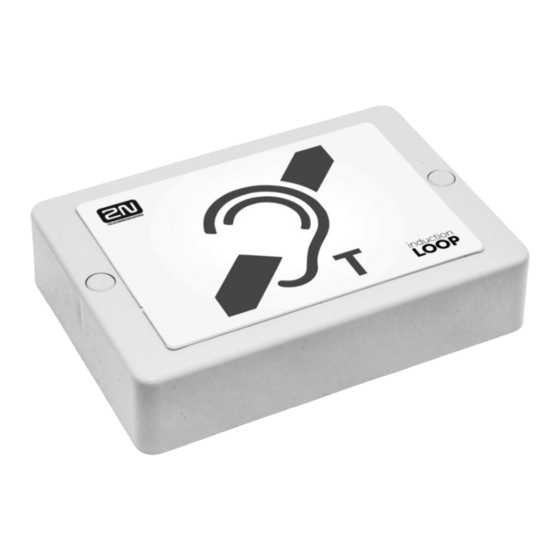
Induction Loop Amplifier – Instructions for Use
2N Telekomunikace a.s.
Version 1.0
Product Description
The device is part of sound system installations for hearing impaired persons that are equipped with a
special hearing aid capable of receiving reproduced sound via a magnetic field receiver. The system is
defined by the IEC 60118-4 standard.
Installation
Amplifier Mounting, version for 2N IP intercom
The induction loop amplifier can be wall mounted with the use of an internal induction loop where a
signal covering is requested. Outdoor use is possible thanks to the IP65 covering. A four-wire cable of
the length of one meter is mounted to the supplied product for easier connection to the intercom. In the
cable are two wires for 12 V DC supply and two wires for signal input, the wires are connected into
interconnection connector. If you shorten the cable, follow the colour marking.
Before wall mounting run the cable through the hole that you have prepared. Then mark two mounting
holes on the wall, through the amplifier front. Remove the amplifier and drill the mounting holes. Use
the plugs and screws included in the delivery. Use a drill of the diameter of 6 mm. After fastening,
cover the screws with the blanks supplied.
Use the supplied connectors to connect the amplifier to the intercom and power supply. The A
connector is connected to the amplifier four-wire cable. Insert a special intercom-connecting cable
supplied with the amplifier and 12 V power supply outlets to the B connector. Connect the special
cable to the intercom and connect the power supply to the mains. You can place the mated A and B
connectors into the 2N IP intercom cover. The connectors help you connect stripped cables. Open the
connector by pushing a thin screwdriver onto the white spots at its front and close the connector by
sliding the movable part through a side gap.
Advertisement

Subscribe to Our Youtube Channel
Summary of Contents for 2N Telekomunikace Induction Loop
- Page 1 Amplifier Mounting, version for 2N IP intercom The induction loop amplifier can be wall mounted with the use of an internal induction loop where a signal covering is requested. Outdoor use is possible thanks to the IP65 covering. A four-wire cable of the length of one meter is mounted to the supplied product for easier connection to the intercom.
- Page 2 Induction loop: When you use the internal induction loop, keep the jumpers on the J1 and J2 headers and let the output terminals unconnected. When you use an external induction loop, disconnect the jumpers from the J1 and J2 headers and connect the induction loop to the output terminals.
- Page 3 This description only relates to the cases in which the amplifier is not used as preset, i.e. connected to 2N IP intercom and using the internal induction loop. When the power supply voltage is activated, the blue “Power” LED lights up. If the LED is not illuminated, the power supply is not connected or its polarity is wrong.
- Page 4 Use this setting for the external loop supplied by 2N too. The setting is suitable for exciting loads of approximately 8 Ω. A lower level of the output signal is suitable for high impedance loads or when a lower intensity of the magnetic field is required.
Need help?
Do you have a question about the Induction Loop and is the answer not in the manual?
Questions and answers