Advertisement
*47344939*
22
47344939
ALK Alarm Kit
Installation Instructions
Index:
• General Information .................. 2
• Parts List ................................... 2
...................................
• Installation ................................ 3
• Wiring ...................................... 5
• Operating Instructions .............. 7
• Changing the Battery ................ 8
Advertisement
Table of Contents

Summary of Contents for Von Duprin ALK
-
Page 1: Table Of Contents
*47344939* 47344939 ALK Alarm Kit Installation Instructions Index: • General Information ....2 • Parts List ........2 ........• Installation ........ 3 • Wiring ........5 • Operating Instructions ....7 • Changing the Battery ....8... -
Page 2: General Information
Review this page carefully. It will help identify the hardware and define the terminology used throughout. Parts List L Note: The ALK Alarm Kit requires an RX or LX switch mounted in the exit device. Kits come standard with the RX switch unless ordered otherwise. -
Page 3: Installation
Installation Assemble the ALK unit with the parts in order as shown below, through 1 1/4" Mortise cylinder Remove and discard with straight cam Make sure (not included in kit) polarity Do not allow is correct pieces to slip out... - Page 4 Cut the device and/or cover plate (end opposite cylinder hole) to proper length. L Note: See device installation instructions for additional information. Cut this end Minimum cover plate length is 8-7/8" If exit device does not have LX or RX switch in it, install switch before proceeding. L Note: Refer to the appropriate RX or LX installation instructions.
-
Page 5: Wiring
The EI (external inhibit) option uses NO (normally open) dry access control contacts to inhibit the ALK. Closing the access control contacts inhibits the ALK. When the access control contacts are re-opened, the ALK re-arms with no delay. RX, LX, and EI inputs are not polarized. - Page 6 Remove dogging shaft if present, install bearing strip, and slide ALK unit into device. L Note: Make sure that the wires do not tangle with moving parts by carefully pulling them toward the dogging end of device while sliding in the ALK unit.
-
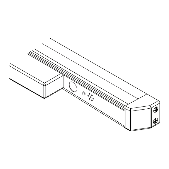
Page 7: Operating Instructions
2. Observe the LED. After the 15-20 second delay has passed, the horn will sound briefly and the LED will flash every 12 to 15 seconds. This indicates that the ALK is now in armed mode. 3. Turn the key counterclockwise to position to disarm. -
Page 8: Changing The Battery
To change the battery, follow steps through below, then reassemble. Remove end cap Remove end cap Remove end cap Remove end cap Slide out ALK assembly Slide out ALK assembly Slide out ALK assembly Slide out ALK assembly Make sure polarity is correct...
Need help?
Do you have a question about the ALK and is the answer not in the manual?
Questions and answers