
Summary of Contents for SAINT-GOBAIN ABRASIVES Norton Clipper C13PE
- Page 1 OWNERS MANUAL Small Concrete Saw Models: C13PE C14PEK FORM: C13PE and C14PEK rev 3-2022...
- Page 2 The responsibility of Norton under this warranty is limited to replacement or repair of defective parts at Saint-Gobain Abrasives, Inc. Stephenville, Texas factory, or at a point designated by it, of such part as shall appear to us upon inspection at such point, to have been defective in material or workmanship, with expense for transportation borne by the customer.
-
Page 3: Table Of Contents
Table of Contents CONTENTS PAGE I. Preparation A. Safety Precautions Dust and Silica Warning B. Assembly C. Specifications: C13PE and C14PEK Series Concrete Saws D. Engine Precautions E. Pointer Alignment II. Operation 9-15 A. Blade Installation 9-10 B. Starting The Engine 10-11 C13PE 13HP Honda 10-12... -
Page 4: Preparation
I. PREPARATION A. Safety Precautions Important! The following safety precautions must always be observed. Hazard Symbols Fuel (gasoline) is extremely flammable and its vapors can explode if ignited. Store gasoline only in approved containers, in well-ventilated, unoccupied approved areas, and away from sparks or flames. -
Page 5: Dust And Silica Warning
Dust and Silica Warning Grinding/cutting/drilling of masonry, concrete, metal and other materials can generate dust, mists and fumes containing chemicals known to cause serious or fatal injury or illness, such as respiratory disease, cancer, birth defects or other reproductive harm. If you are unfamiliar with the risks associated with the particular process and/or material being cut or the composition of the tool being used, review the material safety data sheet and/or consult your employer, the material manufacturer/supplier, governmental agencies such as OSHA and... - Page 6 1. Before mounting any blade on the saw, the blade should be inspected for any damage which might have occurred during shipment, handling or previous use. 2. The blade collars and arbors should be cleaned and examined for damage before mounting the blade. 3.
-
Page 7: Assembly
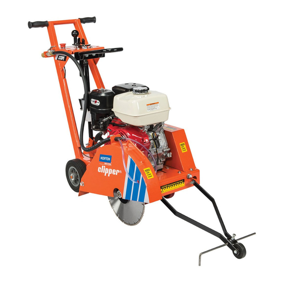
I. PREPARATION B. Assembly The C13PE and C14PEK compact concrete saw is shipped completely assembled and ready for use except for diamond blade, gasoline, and oil. Inspect the saw for shipping damage. If any damage is found, contact the shipper immediately and file a freight claim. Norton Clipper is not responsible for any freight-related damages. -
Page 8: Specifications: C13Pe And C14Pek Series Concrete Saws
* = Horse power and Torque ratings are Gross Horse power and are supplied by the engine manufacturer. Actual output of the engine will vary due to many factors including operational speed of engine, environmental conditions, maintenance, fuel, and other variables. Saint-Gobain Abrasives, Inc. makes... -
Page 9: Engine Precautions
D. Engine Precautions Prior to attempting to operate the engine, read the information contained in the engine owner's manual. An engine owner’s manual is supplied with every gasoline powered concrete saw. 1. Check Oil: Add oil if low. Refer to the engine owner's manual for the recommended SAE viscosity grades. -
Page 10: Starting The Engine
3. Clean off any foreign particles on the clamping surfaces of both collars and on the mounting surface of the blade. 4. Place the blade on the blade shaft, lining up the drive pin hole in the blade with the drive pinhole in the inside collar. For Best Performance Use Only Norton Diamond Blades Specified for the Material Being Cut. - Page 11 Move the choke lever to the CLOSED position. Turn the Fuel Control to the ON Position NOTE: The Choke may not be needed if the engine Located on the Honda Engine under the Air Cleaner is warm or the air temperature is high. ON/OFF Switch Place the Honda engine ON/OFF switch to the ON...
-
Page 12: C14Pek 14Hp Kohler
As the engine warms up, gradually move the choke Position the throttle control lever for the maximum lever to the OPEN position (fully to the right) engine speed (fully to the Left). To stop the engine, move the Throttle Control Lever fully to the Forward Position (fully to the right), press the Emergency Stop Switch (Down Position), and then turn the engine switch to the OFF position. - Page 13 Before starting, insure that the blade is properly installed, all guards are in place and in safe operating condition, and that the Blade is not in contact with any surface or object. Also verify that the area where the work is to be performed is clean, safe, and has proper ventilation and lighting.
-
Page 14: Water Supply
As the engine warms up, gradually move the choke lever to the OPEN position (fully to the right) Position the throttle control lever for the maximum engine speed (fully to the Left). To stop the engine, move the Throttle Control Lever fully to the Slow Position (fully to the right), press the Emergency Stop Switch on the Console, turn the Kohler Engine On/Off switch to the OFF Position, press the Emergency Stop Switch (Down Position), and move the Fuel Control Lever fully to the Right (this... -
Page 15: Cutting Technique
9. Slowly lower the blade by rotating the hand wheel clockwise until the desired depth of cut is reached. Use a reasonable rate of feed. Do not force the blade into the cut!! 10. When the end of the cut is reached, slowly raise the blade out of the cut by rotating the Hand Wheel counter-clockwise until the blade is at least one (1) inch above the ground. -
Page 16: C1318P Honda Powered
Kohler Engine Manual. Norton does not warranty the engine. If any warranty or service of the engine is required contact your nearest engine service center C13PE with Honda GX390 engines: 770-497-6400 https://engines.honda.com/dealer-locator C14PEK with Kohler CH440 engines: 800-544-2444 https://engines.honda.com/dealer-locator Refer to the engine owner’s manual for the engine that is equipped on your machine for owner's manual for complete maintenance, operation, and service information. -
Page 17: C1418P Kohler Powered
Always refer to the engine manual for more detailed information on checking the oil, changing oil, and oil capacity, air filter changes, and fuel type to use. Use only Honda air filters. Do not clean the air filter with gasoline or other flammable solvents. -
Page 18: Dry Cutting Engine Maintenance (Honda And Kohler)
Kohler recommends the use of Kohler branded oils for best performance these are available from your local Kohler servicing dealer. The use of other high quality detergent oils including synthetic that meet the API (American Petroleum Institute) service class of SJ or higher are acceptable. Please select a viscosity based on the environmental air temperature at the time of operation as shown in the table below. -
Page 19: V-Belts
Shaft Size Maximum Grease Capacity of Bearing Chamber in Ounces 1/2"' to 3/4" 7/8" to 1-3/16" 1-1/4" to 1-1/2" Improper Maintenance of Bearings Is Not Covered by Any Warranty. Over Lubrication Will Damage a Bearing. Grease Protruding from the Sides of the Bearing Is a Sign of Over Lubrication. - Page 20 Engine 3/8” Mounting Bolt, Belt Guard qty =4. Note one (1) per corner of engine. Belt Tensioning Assembly 3/8” Belt Guard Retaining Hardware, qty=2. NOTE: One (1) Screw is on the front of the Belt Guard Figure: C13PE and C14PEK Belt Tensioning System 1.
- Page 21 3/8” Jam Nut 3/8” Jam Nut Figure: C13PE and C14PEK Belt Tensioning Assembly 6. To apply tension to the Belts, tighten (turn clockwise) the rear 3/8” Jam Nut until the required Belt Tension is achieved. To loosen the Belts, turn the front 3/8”...
-
Page 22: Belt Alignment
Figure: C13PE and C14PEK Belt Tensioning Jam Nut Directions 7. Tighten the four (4) 3/8” Engine Mounting Bolts. 8. Replace the Belt Guard and replace and tighten the 3/8” Belt Guard Retaining Hardware. 9. Run the machine for around 15 minutes and recheck the belt tension. If the Belts slip under load increase the belt tension. -
Page 23: Main Causes Of Belt Failures
Main Causes of Belt Failures: Premature Belt failure can be attributed to the following issues: Tension (too much or too little), Pulley Misalignment, Damaged Pulleys, Improper Handling or Storage, Incorrect Blade Specification for Material Being Cut, and Cutting Too Deep. Symptom Possible Cause Corrective Action... -
Page 24: Inspection And Cleaning
STOP turning the Depth Control Hand Wheel when resistance is felt. Resistance is a sign that either the full depth or fully raised positions are reached. Continuing to turn the Hand Wheel will result in the breakage of either the flange bearing or stripping of the raise screw which is not considered warranty. -
Page 25: Wiring Diagrams C13Pe And C14Pek
F. Wiring Diagram C13PE 13HP Honda C13PE Honda GX390 Engine... -
Page 26: C1418P Kohler Powered Wiring Diagram
F. Wiring Diagram C14PEK 14HP Kohler C14PEK Kohler CH440 Engine... -
Page 27: Parts List Section
IV. PARTS LIST SECTION A. Ordering Information 1. List model number and serial number of machine. 2. List UPC (Universal Product Code) number and description. Do not list the item number. 3. Wherever alternate parts are shown due to product improvement, inspect the part you have and provide additional description as necessary. -
Page 28: Parts Drawing And Service Parts List
Depth Control and Depth Lock Group... - Page 29 Depth Control and Depth Lock Group UPC No Description Type NOTES Part No 70184647692 Hand Wheel Weldment C13PE/C14PEK 247801 Hand Wheel Body and Raise Screw 70184628279 Ball Knob 238202 70184647693 247805 Screw 1/2"-13 UNC x 3 Socket Head Sold As Each Screw 3/8"-16 UNC x 2-1/2 Hex Head 70184649906 8041056...
-
Page 30: Blade Guard And Water Control Group
Blade Guard and Water Control Group UPC No Description Type NOTES Part No 70184628501 Ring Guard Lock 238223 70184628498 238225 Guard Lock 70184628499 238224 Spring Guard Lock 70184628500 Pin Guard Lock 238222 70184650124 Washer ½” SAE 8172011 Sold as Each Set of two (2) Nozzles 70184681299 Nozzel Water (2) -
Page 31: Engine Group
Engine Group UPC No Description Type NOTES Part No Engine 13HP Honda Manual Start Engine Only. C13PE Model 70184671620 123327 GX390UT2QXC9 Honda Specification GX390UT2QXC9 Engine 14HP Honda Manual Start Engine Only. C14PEK Model PA-CH440-1349 Honda Specification PA-CH440-1349 70184650373 Nut 3/8"-16 UNC Nylock 8160003 70184650123 Washer 3/8 SAE... -
Page 32: Blade Shaft Group
Blade Shaft Group UPC No Description Type NOTES Part No 70184649903 Screw 3/8” -16 x 1-¾” Hex Head Cap 8041053 70184650123 Washer 3/8” SAE 8172009 70184647700 Pulley 4.12OD x 1" B 3G 3V 247302 Includes Set Screws 70184678503 QTY =2 70184678503 Screw 5/16"-18 UNC x 1/4"... -
Page 33: Raise Axle Group
Raise Axle Group UPC No Item Description Type NOTES Part No 70184674553 Pin Cotter 1/8” x 1-½” 227146 70184650129 8172015 Washer ¾” SAE 70184674103 Wheel 8” x 2”-½” x ¾” Rear 227148 Sold Individually (1) 70184647705 Screw ½"-13 UNC x 6-½" Hex Head Cap 247409 70184650123 Washer 3/8”... -
Page 34: Main Frame And Belt Guard Group
Main Frame and Belt Guard Group UPC No Part No Description Type NOTES 70184628074 238213 Wrench Open End 1-½” 70184674393 227101 Hand Grip Sold Individually (1) 70184650123 8172009 Washer 3/8” SAE Sold Individually (1) 70184650149 8177012 Washer 3/8” Spring Lock Sold Individually (1) 70184649901 8041051... -
Page 35: Front Pointer Group
Front Pointer Group UPC No Description Type NOTES Part No Includes: Front Pointer Rod, Pointer Frame, Wheel, and Hardware. NOTE: Hardware in 00310024051 Pointer Assembly 232127 00310024051 is metric but will function without any issues. Pointer Frame Weldment is only available as part of 00310024051 70184649903 Screw 3/8”-16 X 1-¾”... -
Page 36: Optional Water Tank Group C13Pe And C14Pek
Optional Water Tank Group C13PE/C14PEK... - Page 37 Optional Water Tank Group C13PE/C14PEK UPC No Description Type NOTES Part No Optional Water Tank Kit Includes: Water Tank, Cap (Plug), All Fittings shown 70184631499 WATER Tank Assembly C13PE 247120 below, Hose to Blade Guard, and Mounting Hardware 00510069471 WATER Tank Complete 50941 Includes: Water Tank and Stopper (Cap) 00310006560...
-
Page 38: Decals C13Pe And C14Pek
Decals C13PE and C14PEK Operator’s Right Side C13PE and C14PEK... -
Page 39: Operator's Right Side C13Pe And C14Pek
Decals C13PE and C14PEK Operator’s Right Side C13PE and C14PEK Description NOTES Decal Image Top of Raise Screw Handle DECAL RAISE/LOWER 70184632317 C13PE and C14PEK C13PE/C14PE PN: 247306 Top Operator’s Left Side of Fuel Tank 70184674649 DECAL DANGER LETHAL FUMES ALL Models PN: 227243 Front of Belt Guard... -
Page 40: Operator's Left Side C13Pe And C14Pek
Decals C13PE and C14PEK Operator’s Left Side C13PE and C14PEK Operator’s Left Side C13PE and C14PEK Description NOTES Decal Image Top of Console DECAL SAFETY GEAR 70184674481 ALL Models CAUTION PN: 227234 Top of Console DECAL PROPOSITION 65 70184673104 ALL Models WARNING PN: 108934 DECAL MODEL C13PE OPERATOR... - Page 41 Decals C13PE and C14PEK Operator’s Left Side C13PE and C14PEK Description NOTES Decal Image Top of Belt Guard 70184674632 DECAL CAUTION GUARDS ALL Models PN: 227237 Top of Belt Guard 70184674633 DECAL CAUTION BELTS ALL Models PN: 227238 Operators Right Side of Blade Guard and Belt DECAL NORTON CLIPPER LOGO 70184631637...
- Page 42 Saint-Gobain Abrasives 2770 West Washington Stephenville, TX 76401 Phone: 254-918-2310 Fax: 254-918-2312...
Need help?
Do you have a question about the Norton Clipper C13PE and is the answer not in the manual?
Questions and answers