
Summary of Contents for VMS LX2 Series
- Page 1 Laser GRBL LX2b Controller User Manual For use with LightBurn & Laser GRBL Software...
-
Page 2: Copyright Information
(c) Copyright 2022 Velocitronics Motion Systems, Inc. (Vms) The information contained herein is subject to change without notice. The warranties for Vms products and services are set forth in the express warranty statements accompanying such products and services. Nothing herein should be construed as constituting an additional warranty. -
Page 3: Table Of Contents
LX2 Series - Contents Table of Contents User Manual ................................1 Copyright information ............................. 2 Trademark credits ..............................2 Safety and precautionary information ........................2 About this document ............................6 Intended audience ..............................6 System and Software requirements ........................6 Minimum System Requirements .......................... -
Page 4: About This Document
LX2 Series About this document Intended audience This document is intended to be used by individuals who own a K40 or other similar laser engraver and who have purchased the Laser GRBL LX2b board. This document will guide the user on how to safely install the Laser GRBL LX2b board into their K40 or similar laser engraver and to help the user get better acquainted with the features and functions as well as setting up the software and dialing in settings for first time use. -
Page 5: Overview Of The Hardware
16-bit 1000 step grayscale variable laser PWM output with custom configurable PWM options, all axis freewheel or axis locking ability and laser power maximum control. Free firmware updates. The firmware is field upgradeable through the Vms Bootloader Tool. • Power protection 24V power input reverse polarity and surge protection •... -
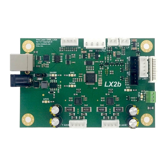
Page 6: Base Board Diagram And Connector Functions
LX2 Series Base Board diagram and connector functions Note: Pin 1 is marked with an ⓫ ❿ ❾ ❽ ❼ ❶ ❻ ❷ ❺ ❸ ❹... -
Page 7: Connector Definitions And Pinout Information
LX2 Series Connector definitions and pinout information Each connector with a┏ marker on the board denotes pin 1 1. USB B connector 6. X-Driver & XY Limit Pin 1 - +5V power Pin 1 – Y-Limit Input Pin 1 – N/C Pin 2 –... -
Page 8: Base Board Diagram And Led Locations
LX2 Series Base Board diagram and LED locations �� �� �� �� �� ��... -
Page 9: Led Definitions And Functions
LX2 Series LED definitions and functions A. 24VG - 24V Power LED D. DONE - Done LED If illuminated the 24V power is ON and the This LED indicates GRBL is running and also turns drivers are powered off and on when settings are updated B. -
Page 10: Hardware Installation
LX2 Series Hardware Installation This procedure is for an M2 Nano controller board replacement in a K40 laser engraver. Since there are many variations of wiring schemes used in different laser engravers this procedure will only cover how to swap out the M2 Nano board and replace it with the Laser GBRL LX2b board. - Page 11 LX2 Series “Ribbon cable” configuration 1: Ribbon Cable Contacts Side...
- Page 12 LX2 Series “Discrete wire” configuration 2:...
- Page 13 LX2 Series 4. Take note of which configuration you have above and begin by removing the cables from the board. When the cables are removed you are now ready to remove the M2 Nano frame from the laser engraver. Pictured here is a K40. If your setup differs from a K40 consult your manual for details on how to remove your board from your laser engraver.
- Page 14 3 of this instruction. Ensure all connectors are securely seated in their respective locations. Congratulations the hardware installation is now complete!! If you did not complete the installation and need further assistance or have questions regarding the installation, please contact Vms for support.
-
Page 15: Lx2B Board Power Up And Initialization
LX2 Series LX2b board power up and Initialization When you are ready, switch on the “Power Switch” & “Lighting Switch” (1) and then turn the main power switch clockwise (2). You may need to release the emergency stop button (3). -
Page 16: Hardware Settings And Software Installation
LX2 Series Hardware Settings and Software Installation Install the USB driver When you are ready, connect the provided USB cable “A” plug into an available USB 2.0 or USB 3.0 port on your PC and the cable “B” plug into the Laser GBRL LX2b board. Below are examples of what a USB “A”... -
Page 17: Lightburn Device Setup
LX2 Series LightBurn Device Setup Find and run LightBurn software by double clicking the icon on the desktop or find it in the start menu. Once open click on Devices button: 2. Once you click on the Devices button you will see a Devices window appear. Since this is a... - Page 18 LX2 Series 3. Once you have clicked on Create Manually button another window will appear. Choose GRBL and then Next as shown: 4. Next another window will appear. Click Next as shown:...
- Page 19 LX2 Series 5. The next window that appears will ask what you would like to call this connection (you can leave it as “GRBL” or you can change it if you choose) and the dimension of the work area in MM. For a standard K40, enter X = 300mm and Y = 200mm then click Next.
- Page 20 LX2 Series 7. Finally, we should see this window when the device has been configured. Click Finish to complete the Device Setup: 8. Go to Device Settings in LightBurn and then change the baud rate to 921600 as shown below:...
- Page 21 LX2 Series 9. You should now be able to connect to the LX2b board. Go to the console tab in LightBurn and observe if the board responds to the wake message. You should see something like this: If the LX2b board does not respond to the wake message automatically, “right-click”...
-
Page 22: Connecting To The Lx4S Board
LX2 Series Connecting to the LX2b Board 1. To connect to the LX2b board click the “Choose” dropdown as shown below and select the com port the LX2b board is connected to. If the drivers were installed correctly the dropdown will automatically populate the com port numbers when LightBurn loads. -
Page 23: Machine Jog X & Y Direction Setup
LX2 Series Machine Jog X & Y Direction Setup Every board that ships have default machine settings for the jog direction. Depending on the motor wiring these may need to be adjusted. To adjust the jog direction, follow the steps below: 1. - Page 24 LX2 Series 2. If the X or Y axis direction is wrong you will need to change the settings for that axis. To change the machine settings, go to Edit and then Machine Settings as shown below:...
- Page 25 LX2 Series 3. Once you click on Machine Settings a properties window will appear. Expand “Outputs setup” by double clicking on it. You will see the X Direction pin invert and Y Direction pin invert as shown below. To change the direction, click on the True or False switch. When you are...
-
Page 26: Y Limit Switch Testing
If the changes have not fixed the jog direction you may need to go back into the Machine Settings to make further changes. If you are having difficulty making these changes, please contact Vms for further assistance. X & Y Limit Switch Testing 1. - Page 27 If you test the X-Axis Limit you should see this in the Console screen: If you test the Y-Axis limit you should see this in the Console screen: If both limits work proceed to the next section. If they do not work, contact Vms for further assistance.
-
Page 28: Homing Direction Setup And Homing
LX2 Series Homing Direction Setup and Homing To properly home the laser engraver we need to setup the homing direction. Since we have tested the limit switches in the last section, we can now check the homing direction and make changes if necessary. - Page 29 250 milliseconds. If the homing cycle is too fast and does not complete properly you can increase this value to give the mechanical system time to engage the limit switch and pull off. If you are still having difficulties homing your machine contact Vms for further assistance.
-
Page 30: Workspace Offset Setup
LX2 Series Workspace Offset Setup In order for the LX2b board to work well with LightBurn the offsets have to be applied correctly. The LX2b board works like most CNC controllers and uses the positive and negative coordinate system. LightBurn uses positive workspace coordinates only. To get around this we need to apply offsets. - Page 31 $RST=# and press Enter This will clear the offsets. To confirm the offset has been cleared type “$#” and press Enter. Note: If you’re having trouble with the offsets or have questions contact Vms for further assistance.
-
Page 32: Steps Per Mm Calibration For X And Y Axes
Next go to Machine Settings or the console to update $100 (X) and $101 (Y). Note: If you’re having trouble calibrating the axes or have questions contact Vms for further assistance. -
Page 33: Laser Power Calibration Procedure
The $36 laser PWM maximum is adjusted based on the maximum laser tube current (mA) set above. You will need the Vms Test Card to adjust the $36 value. Currently there are four test cards 40W, 60W, 80W and 100W. Please contact Vms if you have a laser tube wattage (W) not shown. - Page 34 OK if the values are a little off. As long as all the values scale within the range it will be fine. Shown below is the 40W test card example with the mA range in the red box: Example 1B: Note: If you’re having trouble calibrating laser power or have questions contact Vms for further assistance.
-
Page 35: Rotary Setup And Use
Plug in the rotary cable. There is the option to purchase the Rotary Gantry toggle switch module. If you have purchased this module follow the instructions provided. If you do not have the Rotary Gantry toggle switch module and would like to purchase one contact Vms. 2. Turn on the K40 laser. -
Page 36: Rotary Lightburn Macro Setup
Enter Gantry for the Button Label and enter $101 Y Axis Steps value from grbl settings. $101=80.000 is just an example to show how to enter the string: Note: If you have a custom rotary, having trouble setting it up or have questions contact Vms for further assistance. -
Page 37: Going Further
LX2 Series Going further Congratulations you have successfully setup the LX2b Board with LightBurn! You are now ready to explore the LX2b board’s capabilities. If you have technical related questions or issues regarding the use of LightBurn there is a technical support forum which can be found here: https://forum.lightburnsoftware.com... -
Page 38: Troubleshooting Lx4 Board And Lightburn
Currently working on a program to write registry values to make the com ports “static”. Contact Vms for further details if you have this issue. 3. Laser Engraver moves too fast in between cuts, engraving sections or start and end of a job •... -
Page 39: M7 Air Assist Relay Or Air Valve Control Output
LX2 Series M7 Air Assist Relay or Air Valve Control Output The LX2b board has one output to control air assist, exhaust fan, auxiliary device or function. You can control M7 through LightBurn for automatic air assist. To set up M7 go to LightBurn Device Settings and choose M7: NOTE: You can also test M7 through the LightBurn console. - Page 40 LX2 Series Below is a sample connection to the connector and to the solid-state relay: The solid-state relay used in the diagram is the Fotek SSR-25 DA. Another similar solid-state relay that can be used is the TWTADE SSR-25DA. Both of these solid-state relays can control AC loads.
-
Page 41: Laser Power Supply And Laser Pwm Control Output
LX2 Series Laser Power Supply and Laser PWM Control Output The laser power supply and pwm control output connectors LPAL, AL provide the pwm signals and the power input to the LX2b board. Depending on the laser connection type in the hardware setup some of these connectors are not used. -
Page 42: Jst Xhp Connectors And Part Numbers
LX2 Series JST XHP Connectors and Part Numbers The LX2b Board uses the JST type XHP style connectors for its interconnect standard. There are other Chinese brands that can be purchased from Amazon if desired to terminate your own cables. Below is an example of the XHP connector and the pin #1 mark. -
Page 43: Jst Vhr Connector And Part Number
LX2 Series JST VHR Connector and Part Number The LX2b Board uses the JST type VHR style connector for the four-pin power and PWM signal. There are other Chinese brands that can be purchased from Amazon if desired to terminate your own cables. -
Page 44: Grbl Settings And Definitions
LX2 Series GRBL Settings and Definitions The LX2b Board has a custom version of GRBL. Always make changes to the grbl settings from this list only and not from another source off the internet. To access the settings, go to the LightBurn console and type: $S then press enter. - Page 45 This sets the laser PWM maximum value in a percentage between 0 to 100%. This value is adjusted based on the Vms Test Card created to calibrate laser power. The Test Card comes in different power levels and must be specified at the time of order. See the “Laser Power Calibration Procedure”...
- Page 46 LX2 Series ******** $110, $111 – [X, Y Axis] Max Rate Explanation ATTENTION: The DEFAULT is set to the MAXIMUM the board can go. You will need to adjust this to your stepper motors and mechanics of your laser. This sets the maximum rate each axis can move. Whenever GRBL plans a move, it checks whether or not the move causes any one of these individual axes to exceed their max rate.
-
Page 47: Revision History
LX2 Series Revision History Revision Description of Change Initial Release Changed the wording for homing location, changed 80W mA to 20 and made some other small textual changes. Added Homing Cycle Interrupt Delay and updated other parameters. Made some other small textual changes.
Need help?
Do you have a question about the LX2 Series and is the answer not in the manual?
Questions and answers