Table of Contents
Advertisement
Quick Links
INSTALLATION INSTRUCTIONS
MEMBER
AND OWNERS MANUAL
Part # ISCHX82, Rev 0, 09/2016
w w w . s e a s t a r s o l u t i o n s . c o m
xtreme
CHX8700
CHX8200
ch2200
mt3
MECHANICAL ENGINE CONTROLS
pro-trim
CHX8200 and CHX8700 SERIES
single s
twin s
®
MANUFACTURED BY
MARINE ACQUISITION INCORPORATED
DBA SEASTAR SOLUTIONS
U.S.A.
Advertisement
Table of Contents

Related Manuals for allpa SEASTAR SOLUTIONS CHX8700

Summary of Contents for allpa SEASTAR SOLUTIONS CHX8700
- Page 1 INSTALLATION INSTRUCTIONS MEMBER AND OWNERS MANUAL Part # ISCHX82, Rev 0, 09/2016 w w w . s e a s t a r s o l u t i o n s . c o m xtreme CHX8700 CHX8200 ch2200 MECHANICAL ENGINE CONTROLS pro-trim CHX8200 and CHX8700 SERIES...
- Page 2 MECHANICAL ENGINE CONTROLS CHX DUAL SERIES NOTICE Installer: these instructions contain important safety information and must be forwarded to the boat owner. This SeaStar Solutions Control provides both shift and throttle opera- tion for inboards, outboards, and inboard/outboards. In addition to this control, the following components are required for a complete control system: •...
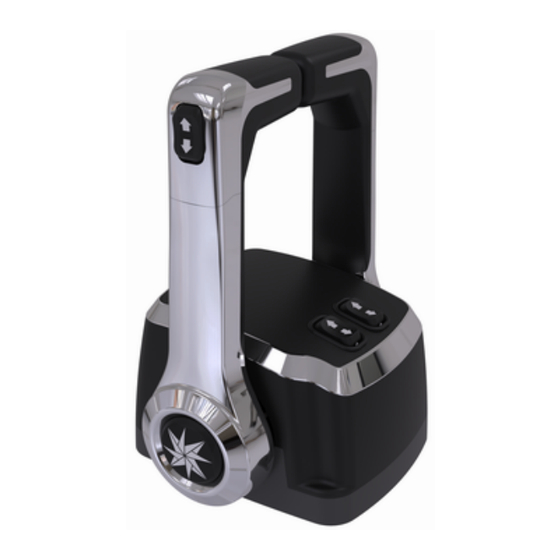
- Page 3 Control Features and Operation (Option Numbers correspond to diagrams below) 1. NEUTRAL THROTTLE WARM-UP CHX 8200/8700 BUTTON. This feature provides a throttle only Dual Top Mount option to warm-up the engine before ControlFeatures driving the boat. When the Control Hand Lever is in Neutral, push and hold the button at the base of the handle.
-
Page 4: Section 1: Location Of Control
Installation SECTION 1: LOCATION OF CONTROL. STEP 1. Allow adequate clearance for hand lever swing (forward and reverse positions). STEP 2. Allow adequate clearance under the console or in the gunwale for the cables AND allow a minimum of 36" from the cable nest con- nection with no restraint. -
Page 5: Installation Of Cables
Installation of Cables A. BEND RADIUS. When routing the control cables, select a path with the minimum number of bends, making the bends as large as possible. Sharp or frequent bends will result in difficult throttle or shift control, loss of motion, and premature cable wear. DO NOT MAKE BENDS OF LESS THAN THE RECOMMENDED MINIMUM BEND RADIUS AS NOTED BELOW. -
Page 6: Section 3: Shift & Throttle Cable Connection-Control End
SECTION 3: SHIFT & THROTTLE CABLE CONNECTION-CONTROL END. •PUSH/PULL refer to the direction of cable motion to shift into “for- ward” or to “open” the throttle. •Refer to the appropriate manufacturer’s manual for shift and throttle direction and adjustments. •Numbered holes on mechanism chassis correspond to holes in shift and throttle levers (for example: connect cable mount to hole 4 on chassis and cable end fitting to hole 4 on lever). - Page 7 Shift Arm Cable Terminal Connection Shift Arm Cable Terminal Connection for “OS” is for 3300/33C Cable. BRP/OMC/Johnson and Evinrude. “KM” is Mercury, MerCruiser. MERCURY GEN II NEST KIT (not included) Cable End Options • 3300/33C (Universal) (note black nest color) •...
-
Page 8: Section 4: Shift & Throttle Cable Connection-Engine End
SECTION 4: SHIFT & THROTTLE CABLE CONNECTION-ENGINE END. CAUTION The throttle cable must be disconnected from the motor before making motor idle adjustments. Adjustment of the motor idle while the throttle cable is connected to the motor may cause jamming action against the idle stop. - Page 9 Abbreviations: Note for Tilt: DN = Down UP = Up 1. Connect Blue and Green together, then Color Key: connect to engine tilt B = Blue signal wire. G = Green V = Violet 2. Connect Red to R = Red engine power wire.
- Page 10 General Control Dimensions CHX8200: DUAL TOP-MOUNT CONTROL GENERAL DIMENSIONS. Exploded View CHX8200 FRICTION ADJUST SCREW. Friction Adjustment of this screw enables the friction in the throttle operating Adjust mechanism to be increased and prevent unwanted handle movement. Screw To adjust, place the lever in the forward or reverse throttle position (just beyond the shift position).
- Page 11 NOTICE This template may not be to scale. Its presence is for information purposes. A separate work template—MT-CHX81 has been included with this control. web: www.seastarsolutions.com SeaStar Solutions 640 North Lewis Road, Limerick, PA 19468 USA...
-
Page 12: Maintenance Notes
Maintenance Notes 1. After a few hours of operation and at frequent intervals thereafter, check all fasteners and the complete control system for security and integrity. DANGER Loosening or loss of one or more fasteners may cause failure of the control system and could cause property damage, injury, or death. - Page 13 © 2016 MARINE ACQUISITION (US) INC. PART # ISCHX82 08-2016 Rev. 0...
Need help?
Do you have a question about the SEASTAR SOLUTIONS CHX8700 and is the answer not in the manual?
Questions and answers