Table of Contents
Advertisement
Quick Links
with Modbus Over RS-485 & Ground Fault Detection
PROTECTOWIRE
FireSystems
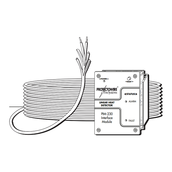
PIM-230 Interface Module
Installation and Operation Guide
An ISO 9001 Registered Company
®
PC-1243
PROTECTOWIRE
RESET
J10
Y1
P1
S2
POWER
POWER
D1
RESET
U2
D63
S1
1
JP14
STATUS
U8
D62
D2
ALARM
K2
ALARM
LINEAR HEAT
DETECTOR
U9
D4
SHORT
K1
PIM-230
D3
Interface
FAULT
K3
FAULT
Module
TP24
Advertisement
Table of Contents

Summary of Contents for Protectowire PIM-230 Series
- Page 1 PROTECTOWIRE ® FireSystems PC-1243 PROTECTOWIRE RESET POWER POWER RESET JP14 STATUS ALARM ALARM LINEAR HEAT DETECTOR SHORT PIM-230 Interface FAULT FAULT Module TP24 PIM-230 Interface Module with Modbus Over RS-485 & Ground Fault Detection Installation and Operation Guide An ISO 9001 Registered Company...
- Page 2 FireSystems MAN-2010 Last modifi ed 10/16/2020 PIM-230 PCA-1243 Revision B Contains updates included in Firmware v2.4 Copyright © 2020 The Protectowire Co., Inc. 60 Washington Street Pembroke, MA 02359 Phone 781-826-3878 • Fax 781-826-2045 E-Mail: pwire@protectowire.com WWW.PROTECTOWIRE.COM PIM-230 Interface Module...
-
Page 3: Table Of Contents
Table of Contents How Digital Linear Heat Detectors Work Introduction to Digital Linear Heat Detection ................. 1 How Digital Linear Heat Detection Works ..................1 The PIM-230 Interface Module General Information ......................... 2 Description ............................2 Specifi cations ............................ 3 Installation and Wiring ........................ - Page 4 Table of Contents Modbus Over RS-485 Operation Guide Descriptions ........................... 11 RS-485 Description ......................11 Modbus Description ......................11 PIM-230 Modbus over RS-485 ..................11 Specifi cations ..........................11 Port Specifi cations ......................11 Protocol Information ......................11 RS-485 Wiring Wiring Description ......................
-
Page 5: Introduction To Digital Linear Heat Detection
Introduction to Digital Linear Heat Detection Technology Protectowire Linear Heat Detector is a sensor cable that detects heat anywhere along its length. The sensor cable is comprised of two steel conductors individually insulated with a heat sensitive polymer. The insulated conductors are twisted together to impose a spring pressure between them, then wrapped with a protective tape and fi... -
Page 6: The Pim-230 Interface Module
TP24 General Information The Protectowire PIM-230 is a detection control module that provides an interface between a main fi re alarm control panel detection circuit or addressable node and Protectowire Digital Linear Heat Detector. The mod- ule provides one (1) supervised detection circuit that may be fi eld wired for either Class A (Style D) or Class B (Style B) service. -
Page 7: Specifi Cations
End of Line Resistor, 10K Ohm 1/2W Inputs • One initiating device circuit capable of monitoring up to 6,560 Feet (2000 Meters) of Protectowire PHSC and PLR Digital Linear Heat Detectors. Minimum conductor size is 20AWG (0.812mm), or as require by local code. -
Page 8: Installation And Wiring
PIM-230 as close to the area of detection as possible. Wiring Diagram RESET SWITCH PC-1243 PROTECTOWIRE PIM-230 POWER Interface Contact wiring 12 AWG to 30 AWG. When INDICATOR using maximum of two conductors within a single FIELD WIRING DIAGRAM terminal;... -
Page 9: Detector Wiring
Class A (Style D) or Class B (Style B)service. The alarm initiating circuit is capable of operating up to 6,560 feet (2000 meters) of Protectowire Digital Linear Heat Detector. The PIM-230 initiation circuit is designed to monitor Protectowire Digital Linear Heat Detector and also supports other types of normally open contact alarm initiating devices. -
Page 10: Confi Guration & Feature Selection
Indicators, Confi guration & Controls - The PIM-230 has an integrated set of status indicators, DIP switches for confi guration and a reset switch for restoring the status to normal after an event has been cleared. PC-1243 PROTECTOWIRE RESET PC-1243 PROTECTOWIRE... -
Page 11: Operation And Testing
fi eld wired for either Class A (Style D) or Class B (Style B) service. This initiating device circuit is capable of operating up to 6,560 feet (2000 meters) of Protectowire Digital Linear Heat Detector or equivalent com- bination of detector and feed cable. See Figure 8 for an example of a typical fi eld wiring for Class A and B confi... -
Page 12: Test Open Circuit Monitoring
Figure - 8 Step 1 - Test Open Circuit Monitoring - At the end of the Protectowire Linear Heat Detector, open the circuit by disconnecting one leg of the detector from the ELR, see Figure 9, or return fi eld terminals, see Figure 10. -
Page 13: Test Alarm Monitoring
FAULT Step 2 - Test Alarm Monitoring - At the end of the Protectowire Linear Heat Detector, connect a jumper lead across both legs of the detector at the ELR, see Figure 11 or return fi eld terminals, see Figure 12. -
Page 14: Ground Fault Detector
After approximately 10 seconds the PIM-230 “ALARM” turn ON steady indicating an alarm condition. Any remote device monitoring the PIM-230 status should indicate an alarm condition. Remove the short and reset the interface module to return to a normal standby condition. PIM-230 Alarm Status Indicator STATUS ALARM... -
Page 15: Modbus Over Rs-485 Operation Guide
PC-1243 PROTECTOWIRE RESET PC-1243 PROTECTOWIRE RESET Modbus Over RS-485 POWER POWER POWER RESET Operation Guide JP14 JP14 STATUS ALARM ALARM ALARM LINEAR HEAT DETECTOR SHORT PIM-230 Interface FAULT FAULT FAULT Module TP24 TP24 RS-485 Description RS-485 is a standard which describes a physical layer utilized in serial communication. RS-485 allows for installation of inexpensive local network systems and supports multi-drop communication links. -
Page 16: Rs-485 Wiring
(+) and receive (-) terminals respectively. The module does not support full duplex operation. Wiring Diagram - Figure 1 Modbus over RS-485 is PC-1243 PROTECTOWIRE RESET intended to provide ancil- POWER POWER RESET lary information. -
Page 17: Confi Guration Settings
Confi guration Settings Once properly wired to the communication bus each module must be confi gured to communicate on the network. The following network settings must be known before confi guring the module. Slave Address - Each device is assigned a unique slave address to identify it on the network. The Modbus protocol specifi... -
Page 18: Setting The Parity
Setting the Parity - The PIM-230 parity setting can be read and written at holding register 40054. Writing a value from 0 to 2 will set the PIM-230 slave address to the written value. Be aware that changing the parity will break communications until the master device is updated with the new parity value. -
Page 19: Initialize / Reset
Table 5. Status Bits Assignments Ground Menu Alarm Alarm General General Reserved None None Open None Fault Accessed Return Alarm Fault Table 6. Status Bits Event Grid < Bit Normal Normal then > Menu Access Class B Status Events Normal then > Open Class B Alarm Class A Status Events Alarm present on Out, Return Open... - Page 20 POWER J11 DET. CKT. +24 COM GND OT- RT+ RT- Page 16...
- Page 21 Installation Notes ___________________________________________________________________________________ ___________________________________________________________________________________ ___________________________________________________________________________________ ___________________________________________________________________________________ ___________________________________________________________________________________ ___________________________________________________________________________________ ___________________________________________________________________________________ ___________________________________________________________________________________ ___________________________________________________________________________________ ___________________________________________________________________________________ ___________________________________________________________________________________ ___________________________________________________________________________________ ___________________________________________________________________________________ ___________________________________________________________________________________ ___________________________________________________________________________________ ___________________________________________________________________________________ ___________________________________________________________________________________ ___________________________________________________________________________________ ___________________________________________________________________________________ ___________________________________________________________________________________ ___________________________________________________________________________________ ___________________________________________________________________________________ ___________________________________________________________________________________ ___________________________________________________________________________________ ___________________________________________________________________________________...
- Page 22 PROTECTOWIRE ® FireSystems © 2020 The Protectowire Co., Inc. 60 Washington Street Pembroke, MA 02359• Phone 781-826-3878 • Fax 781-826-2045 E-Mail: pwire@protectowire.com WWW.PROTECTOWIRE.COM MAN-2010...
Need help?
Do you have a question about the PIM-230 Series and is the answer not in the manual?
Questions and answers