Advertisement
Quick Links
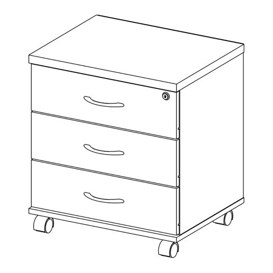
ASSEMBLY INSTRUCTION
HARDWARE ITEM
A2
Screw m3.5 x 14mm
A6
Screw m4 x 25mm
A10
Screw m4 x 38mm
Screw JCBCW
A16
m6 x 50mm
Euro Screw
A34
m5 x 8mm
C7
3 Way Drawer Lock
D4
Wood Dowel 6 x 25mm
Mini Fix 15mm
F2
H3
Handle 96mm
M5
Drawer Metal Slide 300mm
N1
Allen Key
N3
Nail
Single Plastic Cap
R2
W1
Plate Caster Wheel P40
CAUT ION
MATERIAL USE LAMINATED PARTICLE BOARD, TO CLEAN USE
SOFT, DRY CLOTH. DO NOT USE DETERGENT OR CHEMICAL
AVOID CONTACT WITH WATER AND DIRECT SUNLIGHT. TO BE
ASSEMBLED ON A SOFT, DRY, CLEAN SMOOTH SURFACE.
MODEL CODE: 248-000015
QTY
62
COMPLETE
6
12
4
9
12
1
1
Set
6
2
10
Sets
3
2
3
Sets
1
24
(+-3)
12
1
Set
USE OF POWER TOOLS TO ASSEMBLE THIS
PRODUCT WILL INVALIDATE ANY CLAIM AND
MAY DAMAGE THIS PRODUCT MAKING IT
UNSAFE.
PRE - ASSEMBLY
Check and ensure the dimension between the Lock Stopper are the same as
STEP 1
stated in the diagram below.
3 Way Drawer Lock
STEP 2
Insert the Mini Fix Bolt (F2) at panel no. 9. Then, assemble the Plastic Caster
Wheel P40 (W1) at panel no. 7 by using Screw m3.5 x 14mm (A2).
6
F2
F2
9
STEP 3
Slide the 3 Way Drawer Lock (C7) along the groove and assemble the 3 Way
Drawer Lock (C7) at marking hole by using Screw m3.5 x 14mm (A2) at panel
no. 6. Insert the Mini Fix Cam (F2) & assemble Drawer Metal Slide 300mm
(M5) by using Euro Screw m5 x 8mm (A34) at panel no. 5 & 6.
2nd
A34
M5
M5
M5
135mm
133mm
400mm
Lock Stopper
C7
A2
W1
F2
W1
F2
7
W1
F2
W1
F2
F2
F2
F2
F2
M5
M5
5
6
PAGE 1 - 3
47mm
W1
1st
C7
A2
C7
Advertisement

Related Manuals for pakoworld 248-000015


Summary of Contents for pakoworld 248-000015
- Page 1 ASSEMBLY INSTRUCTION MODEL CODE: 248-000015 PAGE 1 - 3 PRE - ASSEMBLY HARDWARE ITEM Check and ensure the dimension between the Lock Stopper are the same as STEP 1 stated in the diagram below. Screw m3.5 x 14mm 47mm 135mm...
- Page 2 ASSEMBLY INSTRUCTION MODEL CODE: 248-000015 PAGE 2 - 3 Insert the Mini Fix Bolt (F2) & assemble the Handle (H3) by using Screw m4 x 25mm (A6) Assemble the panel no. 3, 4 & 8 together by using Screw m4 x 38mm (A10). Assemble 3...
- Page 3 ASSEMBLY INSTRUCTION MODEL CODE: 248-000015 PAGE 3 - 3 Assemble the panel no. 5, 6 & 7 together by using Screw JCBCW m6 x 50mm (A16). STEP 8 STEP 9 Assemble the panel no. 9 to the unit by using Mini Fix 15mm (F2).
Need help?
Do you have a question about the 248-000015 and is the answer not in the manual?
Questions and answers