Table of Contents
Advertisement
Quick Links
TOYOTA COMPUTERIZED EMBROIDERY SYSTEM
INSTRUCTION MANUAL
Before using the embroidery machine, please read through this manual
carefully for proper use of the machine.
After reading the manual, keep it at a safe place near the machine so that
you can consult it whenever it is necessary.
When you turn over the machine to somebody, make sure to attach this
manual to the machine.
Since this is a business use machine, it should be operated by operators
who are well versed in the basic operations.
Advertisement
Table of Contents

Summary of Contents for AISIN SEIKI TOYOTA EXPERT ESP9100 NET
- Page 1 TOYOTA COMPUTERIZED EMBROIDERY SYSTEM INSTRUCTION MANUAL Before using the embroidery machine, please read through this manual carefully for proper use of the machine. After reading the manual, keep it at a safe place near the machine so that you can consult it whenever it is necessary. When you turn over the machine to somebody, make sure to attach this manual to the machine.
-
Page 2: Table Of Contents
CONTENTS SAFETY PRECAUTIONS (Make sure to read the following before use) PART NAMES CHECKING THE PARTS - - - - - - - - - - - - - - - - - - - - - - - 6 ACCESSORIES - - - - - - - - - - - - - - - - - - - - - - - - - - - - - 7 EMBROIDERY MACHINE - - - - - - - - - - - - - - - - - - - - - - 8 OPERATION PANEL BOX - - - - - - - - - - - - - - - - - - - - - - 9... - Page 3 SAFETY PRECAUTIONS (Make sure to read the following before use) Safety precautions are provided to prevent risks and losses which could result from incorrect handling. Please read carefully and comply strictly with them. Meaning of " DANGER", " WARNING" and " CAUTION"...
- Page 4 DANGER Do not open the power supply box. Otherwise, you may sustain electric shock. WARNING Carry the machine by two or more persons. Falling the machine may cause injury as well as breakdown of the machine. When carrying the machine, hold the machine at the positions specified by the label. Falling the machine may cause injury as well as breakdown of the machine.
- Page 5 CAUTION Do not use the machine in areas where strong electric field or magnetic field is generated by a high-power high-frequency motor generator or high-frequency welder. Otherwise the machine will malfunction to cause injury or machine trouble. Place the machine on a sturdy base. Otherwise the machine may fall to cause injury or machine trouble.
- Page 6 Positions and Contents of the Warning Labels For abnormal conditions. Immediately press the eme- CAUTION CAUTION rgency suspension switch to MACHINE stop the embroidering machine. ATTENTION En cas de conditions anormales, Fingers might be injured. ATTENTION pousser immédiatement sur Do not put your hand on hoop while in motion. le bouton d’arrêt d’urgence pour Do not put your finger or hand inside thread stopper la brodeuse.
-
Page 7: Part Names
PART NAMES CHECKING THE PARTS After unpacking the machine, check to be sure that all of the items below have been delivered. ● Embroidery machine (1 set) ● Table (1 pc.) ● Power cord ● Power supply box (1 pc.) AC power cord (1 pc.) DC power cord (1 pc.) * An additional AC power cord and plug for 250 V... -
Page 8: Accessories
ACCESSORIES * We reserve the right to Instruction manual Parts catalogue Vibration-preventive ● ● ● (1 copy) rubber (H) (1 copy) change the contents of this (This book) instruction manual without prior notice. INSTRUCTION PARTS MANUAL CATALOGUE ● Tools (2) Aluminum bobbin 2 pcs. (3) Bobbin case 1 pc. -
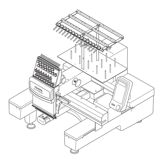
Page 9: Embroidery Machine
EMBROIDERY MACHINE Thread guide Sub thread tension regulator Tension base cover Spiral tube Thread tension regulator Thread stand shaft Tension base Operation panel box Thread stand stud (For details, refer to Page 9.) Color change motor Under thread winder Take-up lever Thread take-up cover Thread hook motor Jump motor... -
Page 10: Operation Panel Box
OPERATION PANEL BOX Function menu key Hoop menu key Edit key Color change key Data set menu key LCD screen DIP switches (For details, refer to Page 10.) Escape key Ten keys (numeric keys) Clear key :Used for a needle bar number Set key of 10 or larger Trace key... -
Page 11: Dip Switches
DIP SWITCHES DIP switch ON or OFF is set as follows: DSW 2 Function * Two-way communica- PC connection Older mode tions (Standard) PC connection * Normal operation Synchronous operation − Not used *Select OFF. − Not used *Select OFF. *Adjustment for stitch Satin stitch width Adjustment for stitch... -
Page 12: Preparation
PREPARATION ASSEMBLING ● Preparation of the thread guide Loosen the pair of set screws (3) for thread stand shaft (1) using an allen wrench and lift the thread guide (4) right above. Thread guide (4) Securely tighten the pair of set screws (3) using an allen wrench, at the position where the top of thread stand shafts (1) and the position align- ment line (5) of the thread stand shaft (2) is... -
Page 13: Carrying
CARRYING As shown in the illustration below, hold the machine at the positions indicated in the label by two or more per- sons to carry the machine. WARNING ATTENTION CARRYING Carry the machine with Il faut être au moins 2personnes at least two people. -
Page 14: Wiring
WIRING Make sure that the power switch (2) of the power supply box (1) is OFF. Insert the plug (4) of the DC power cord (3) securely into the power supply connector (5) of the embroidery machine. Insert the other plug (6) of the DC power cord (3) securely into the DC power supply connector (7) of the power supply box (1). -
Page 15: Connecting The Usb Fdd (Floppy Disk Drive) (To Be Purchased Separately)
CONNECTING THE USB FDD (FLOPPY DISK DRIVE) (TO BE PURCHASED SEPARATELY) Remove the pair of cover set screws (1) and then remove the connector cover (2). Insert the plug (3) of the FDD securely into the USB connector (4) of the embroidery machine. Embroidery machine Floppy disk drive... -
Page 16: Setting The Upper Thread
SETTING THE UPPER THREAD Upper Thread Setting Fig. A Passing the Upper Thread: Procedure Thread guide Spool to Thread Guide 1. Pass the thread from the (10) spool (1) through the hole (13) on the thread guide (1) just above the spool (1) (11) and further pass it through (14) - Page 17 10. Run the thread from the sub thread tension regulator (15) through the spiral tube (15). 11. Run the thread further through the thread guide (15)-1, thread tension regulator (15) rotary sensor (15) and thread guide (15)-2. 12. Open next the needle bar case cover. 13.
-
Page 18: Setting The Under Thread
SETTING THE UNDER THREAD Orient the bobbin (1) with its thread facing in the direction, specified by the arrow symbol, and put it in the bobbin case (2). Route the thread through the thread groove (3) in the bobbin case, under the thread tension spring (4) and the thread guard (5). -
Page 19: Setting The Fabric On The Hoop
SETTING THE FABRIC ON THE HOOP Place the fabric (2) on the outer hoop (1) and press the inner hoop (3) into the outer hoop (1). If the inner hoop (3) cannot be pressed into the outer hoop (1) smoothly, loosen the hoop set screw (4). Check if the fabric is correctly set in the hoop by pressing the center of the fabric gently with the finger as shown in the illustration below. -
Page 20: Setting The Hoop To The Embroidery Machine
SETTING THE HOOP TO THE EMBROIDERY MACHINE Attach two holder bases (1) to the joint plate (2) in the direction indicated by symbol and secure them in place with screws (3). Determine the holder base (1) attaching position meeting the size of the hoop. Insert the right and left metallic tabs of the embroidery hoop set in the sections A and B in the direction of dashed line arrows and fix the tabs by engaging the hoop presser springs (4) of the holder bases (1) in the tabs. -
Page 21: Attaching The Table
ATTACHING THE TABLE Push in the table (1) till it hits the bottom with care to maintain equally at both right and left of top of the base cover (2) on the embroidery machine. Tighten the right and left fixing screws (3). This completes the attaching of the table. Fixing screw (3) Base cover (2) Base... -
Page 22: Winding The Under Thread
WINDING THE UNDER THREAD Set a bobbin (2) on the under thread winding shaft (1). Place the spool (3) on the spool stand on the cover, pass the thread end through the thread tension regulator guide (4) and wind the thread round the bobbin (2). Press the thread winder lever (5) to the right so that it touches the inner face of the bobbin (2). -
Page 23: Checkups Before Starting Operation
CHECKUPS BEFORE STARTING OPERATION Before starting the machine, carry out checkups as indicated below. CAUTION Turn the main switch OFF before checking the machine prior to starting the operation. If you check the machine without turning the main switch OFF, you could sustain injury. Check Point Description Action... -
Page 24: Checking The Embroidery Head
CHECKING THE EMBROIDERY HEAD Check of the Color Change Device and Set Screw The color change device selects needle bars. The machine will fail to operate if the color change cam is off the prede- termined position (set screw is positioned right above or right below). Turn the handle of the color change device to bring the set screw to the top position. -
Page 25: Operation Procedure
OPERATION PROCEDURE 《OPERATION BASICS》 STARTING AND STOPPING THE MACHINE Power Switch The power switch is provided on the power supply box. Press the power switch at "O" side to turn the power OFF or at "I" to turn the When reapplying the power, turn power ON. -
Page 26: Steps To Start Embrodiery
STEPS TO START EMBRODIERY Example: To input the design data using the flat hoop from USB FDD (to be purchased separately) 1 Turn ON the power switch at the power supply box. 2 Select "FLAT" for "HOOP" using (hoop travel keys). 3 Select "ON"... - Page 27 11 Input the needle numbers in the order of needle change using the numeric keys. 12 Press the SET key. = = = C O L O R C H A N G E = = = M O D E A U T O Press 0 1 / 0 4 :...
-
Page 28: Screens
SCREENS The LCD screen displays variety of information to navigate the operation. The information displayed on the LCD screen is briefly explained below. ● Basic Menu Hoop mode (FLAT / CAP / SLEEVE / BORDER / X-PANT) = = = = E S P 9 1 0 0 N E T = = = = Change the selection with the hoop travel keys H O O P F L A T... - Page 29 ● Function Menu: Pressing in "EMB START" mode. Screen (ST: Stitch / rpm: Speed) Change the selection with the hoop travel keys Thread breakage sensor (OFF / 1 - 5) = = = F U N C T I O N M E N U = = 1 S C R E E N Change the selection with the hoop travel keys 2 .
- Page 30 ● Hoop Menu: Pressing in "EMB START" mode. Hoop type (FLAT / CAP / SLEEVE / BORDER / X-PANT) Change the selection with the hoop travel keys Initialization (ON / OFF) = = = = = H O O P M E N U = = = = 1 H O O P * F L A T Change the selection with the hoop travel keys...
- Page 31 ● Data Set Menu: Pressing in "EMB START" mode. Data input device (PC: Serial port / USB: FDD, USB memory) = = = = = D A T A M E N U = = = = 1 I N P U T D A T A Select with the hoop travel keys , and confirm 2 .
- Page 32 Memory-stored design deletion = = = = = D A T A M E N U = = = = 1 . I N P U T D A T A Press the SET key 2 . S E L E C T D A T A 3 D E L E T E D A T A *Selecting the design Memory No.
- Page 33 ● Color Change Setting: Pressing in "EMB START" mode. *In automatic color change mode = = = C O L O R C H A N G E = = = Color change mode (AUTO / MANUAL) M O D E A U T O Press the color change mode key to select.
-
Page 34: Function Menu
《FUNCTION MENU》 CHANGING DISPLAY Sets the information to be displayed during embroidering - number of stitches [*1] or main shaft speed 1 Change the display to FUNCTION MENU. = = = = = E M B S T A R T = = = = A I S I N 1 2 3 . -
Page 35: Thread Break Sensor
THREAD BREAK SENSOR Sets the thread break detection sensing level. 1 Change the display to FUNCTION MENU. = = = = = E M B S T A R T = = = = A I S I N 1 2 3 . 1 0 O Press 1 0 2 7 0 1 / 1 5 : 2 3 4 5 6 7 8 9 A B <... -
Page 36: Bobbin Counter (Set)
BOBBIN COUNTER (SET) Sets the number of stitches for stopping the machine automatically. When the counted number of stitches reaches the preset number, the machine stops automatically. 1 Change the display to FUNCTION MENU. Determine the number of stitches = = = = = E M B S T A R T = = = = to be set for bobbin counter so that A I S I N 1 2 3 . -
Page 37: Bobbin Counter (Counter)
BOBBIN COUNTER (COUNTER) [*1] Clears the counted number of stitches 1 Change the display to FUNCTION MENU. = = = = = E M B S T A R T = = = = A I S I N 1 2 3 . 1 0 O Press 1 0 2 7 0 1 / 1 5 : 2 3 4 5 6 7 8 9 A B <... -
Page 38: Lock Stitch
LOCK STITCH Sets "lock stitch" at the start and end of sewing. 1 Change the display to FUNCTION MENU. = = = = = E M B S T A R T = = = = A I S I N 1 2 3 . 1 0 O Press 1 0 2 7 0 1 / 1 5 : 2 3 4 5 6 7 8 9 A B <... -
Page 39: Satin Adjustment
SATIN ADJUSTMENT Sets adjustment of satin stitch width. 1 Change the display to FUNCTION MENU. = = = = = E M B S T A R T = = = = A I S I N 1 2 3 . 1 0 O Press 1 0 2 7 0 1 / 1 5 : 2 3 4 5 6 7 8 9 A B <... -
Page 40: Slow Start
SLOW START Sets the number of main shaft rotations for which the main shaft rotates at a slow speed when starting sewing after thread trimming. 1 Change the display to FUNCTION MENU. = = = = = E M B S T A R T = = = = A I S I N 1 2 3 . -
Page 41: Trimming In Jump
TRIMMING IN JUMP Inserts thread trimming to stitches of consecutive jumps. Thread is trimmed using the con- tinuous jump signals. 1 Change the display to FUNCTION MENU. = = = = = E M B S T A R T = = = = A I S I N 1 2 3 . -
Page 42: Jump Length
JUMP LENGTH Sets the condition (length) for converting stitches into jump. Stitches longer than the set length are converted into jump. 1 Change the display to FUNCTION MENU. = = = = = E M B S T A R T = = = = A I S I N 1 2 3 . -
Page 43: Trimming Length
TRIMMING LENGTH Sets the length of thread to be trimmed. 1 Change the display to FUNCTION MENU. = = = = = E M B S T A R T = = = = A I S I N 1 2 3 . 1 0 O Press 1 0 2 7 0 1 / 1 5 : 2 3 4 5 6 7 8 9 A B <... -
Page 44: Trimming Timing
TRIMMING TIMING Sets the timing for starting trimming. 1 Change the display to FUNCTION MENU. = = = = = E M B S T A R T = = = = A I S I N 1 2 3 . 1 0 O Press 1 0 2 7 0 1 / 1 5 : 2 3 4 5 6 7 8 9 A B <... -
Page 45: Boring
BORING 1 Change the display to FUNCTION MENU. The boring device should be set on = = = = = E M B S T A R T = = = = the rightmost needle*. A I S I N 1 2 3 . 1 0 O Press 1 0 2 7 0 1 / 1 5 : 2 3 4 5 6 7 8 9 A B <... -
Page 46: Cording
CORDING 1 Change the display to FUNCTION MENU. The cording device should be set = = = = = E M B S T A R T = = = = on the leftmost needle (No. 1 nee- A I S I N 1 2 3 . 1 0 O dle). -
Page 47: Hoop Menu
《HOOP MENU》 HOOP MODE Sets the embroidery hoop type - flat / cap / sleeve / border / X-Panto. 1 Change the display to HOOP MENU. Change the embroidery hoop type = = = = = E M B S T A R T = = = = according to the hoop you to be A I S I N 1 2 3 . -
Page 48: Initialization
INITIALIZATION Sets if initial point is searched for when the power is turned ON. 1 Change the display to HOOP MENU. = = = = = E M B S T A R T = = = = A I S I N 1 2 3 . 1 0 O Press 1 0 2 7 0 1 / 1 5 : 2 3 4 5 6 7 8 9 A B <... -
Page 49: Start Point Return Mode
START POINT RETURN MODE Sets the mode (automatic/manual) to move the hoop to the start point. 1 Change the display to HOOP MENU. = = = = = E M B S T A R T = = = = A I S I N 1 2 3 . -
Page 50: Manual Speed
MANUAL SPEED Sets hoop travel speed. 1 Change the display to HOOP MENU. = = = = = E M B S T A R T = = = = A I S I N 1 2 3 . 1 0 O Press 1 0 2 7 0 1 / 1 5 : 2 3 4 5 6 7 8 9 A B <... -
Page 51: Hoop Timing
HOOP TIMING Sets the hoop drive start timing. 1 Change the display to HOOP MENU. "CAP" and "SLEEVE" hoop timing = = = = = E M B S T A R T = = = = are 250° only. A I S I N 1 2 3 . -
Page 52: Offset
OFFSET Sets if the hoop automatically travels to the offset position. For details of offset, refer to Pages 76 and 77. 1 Change the display to HOOP MENU. = = = = = E M B S T A R T = = = = A I S I N 1 2 3 . -
Page 53: Trace Mode
TRACE MODE 1 Change the display to HOOP MENU. = = = = = E M B S T A R T = = = = A I S I N 1 2 3 . 1 0 O Press 1 0 2 7 0 1 / 1 5 : 2 3 4 5 6 7 8 9 A B <... -
Page 54: Edit
《EDIT》 SIZE For details of mirror, refer to Page 83. 1 Change the display to EDIT MENU. = = = = = E M B S T A R T = = = = A I S I N 1 2 3 . 1 0 O Press 1 0 2 7 0 1 / 1 5 : 2 3 4 5 6 7 8 9 A B <... -
Page 55: Design Rotation
DESIGN ROTATION 1 Change the display to EDIT MENU. = = = = = E M B S T A R T = = = = A I S I N 1 2 3 . 1 0 O Press 1 0 2 7 0 1 / 1 5 : 2 3 4 5 6 7 8 9 A B <... -
Page 56: Mirror
MIRROR 1 Change the display to EDIT MENU. For details of mirror, refer to Page = = = = = E M B S T A R T = = = = A I S I N 1 2 3 . 1 0 O Press 1 0 2 7 0 1 / 1 5 : 2 3 4 5 6 7 8 9 A B <... -
Page 57: Design Repeat
DESIGN REPEAT 1 Change the display to EDIT MENU. For details of repeat, refer to Page = = = = = E M B S T A R T = = = = A I S I N 1 2 3 . 1 0 O Press 1 0 2 7 0 1 / 1 5 : 2 3 4 5 6 7 8 9 A B <... - Page 58 7 Select the setting for "X TIMES". X TIMES: 01 - 99 = = R E P E A T S E T T I N G = = Select a value between "1"and "99" P R I O R V E R T I C A L using the following keys: X T I M E S...
- Page 59 13 Select the setting for "Y SPACE". Y SPACE: 0 - 255mm = = R E P E A T S E T T I N G = = Select a value between "0mm"and Y T I M E S "255mm"...
-
Page 60: Color Change Setting
《COLOR CHANGE SETTING》 COLOR CHANGE MODE Sets the color change mode - automatic or manual. 1 Change the display to COLOR CHANGE. = = = = = E M B S T A R T = = = = A I S I N 1 2 3 . 1 0 O Press 1 0 2 7 0 1 / 1 5 : 2 3 4 5 6 7 8 9 A B <... -
Page 61: Needle Bar Setting (Input)
NEEDLE BAR SETTING (INPUT) Sets the needle bar step at the screen. 1 Change the display to COLOR CHANGE. = = = = = E M B S T A R T = = = = A I S I N 1 2 3 . 1 0 O Press 2 4 5 1 0 1 / 0 4 :... -
Page 62: Needle Bar Setting (Change)
NEEDLE BAR SETTING (CHANGE) Changes the needle bar number of a desired step. 1 Change the display to COLOR CHANGE. = = = = = E M B S T A R T = = = = A I S I N 1 2 3 . 1 0 O Press 1 0 2 7 0 1 / 9 9 : 2 3 4 5 6 7 8 9 A B <... -
Page 63: Pause Setting
PAUSE SETTING Sets for pausing of sewing after color change. 1 Change the display to COLOR CHANGE. = = = = = E M B S T A R T = = = = A I S I N 1 2 3 . 1 0 O Press 1 0 2 7 0 1 / 1 5 : 2 3 4 5 6 7 8 9 A B <... -
Page 64: Data Set Menu
《DATA SET MENU》 DATA INPUT (USB FDD) The following explains the procedure for inputting the design data from floppy disk to the machine. The input design data is set as the embroidery data. 1 Insert the floppy disk to floppy disk drive. 2 Change the display to DATA MENU. - Page 65 7 Set the needle bar steps (Example: 11 (B), 5, 7, 3). 7 8 9 0 = = = C O L O R C H A N G E = = = M O D E A U T O 4 5 6 1 2 3 0 1 / 0 4 :...
-
Page 66: Data Input (Pc)
DATA INPUT (PC) The following explains the procedure for inputting the design data from an external device connected to the serial port to the machine (PC). The input data is set as the embroidery data. 1 Remove the connector cover. 2 Connect the external device to the serial port of the machine. - Page 67 9 Press [SET] (Example: In case of design No. 1). When you press the SET key after = = = I N P U T T H R U P C = = inputting the design number regis- Press the keys in the order of N U M B E R tered in the external device, data N A M E...
-
Page 68: Data Input (Lan)
DATA INPUT (LAN) The following explains the procedure for inputting the design data from an external device connected to the LAN port. The input data is set as the embroidery data. 1 Remove the connector cover. 2 Connect the external device to the LAN port of the machine. Before connecting an external LAN Cable device (PC) to the machine (LAN... - Page 69 9 Press [SET] (Example: In case of design No. 1). When you press the SET key after = = = I N P U T T H R U P C = = inputting the design number regis- Press the keys in the order of N U M B E R tered in the external device, data N A M E...
-
Page 70: Data Select
DATA SELECT The following explains the procedure for setting the memory stored design data as the data for embroidery. 1 Change the display to DATA MENU. = = = = = E M B S T A R T = = = = A I S I N 1 2 3 . -
Page 71: Data Deletion
DATA DELETION The following explains the procedure for deleting the design data stored in memory of the machine. 1 Change the display to DATA MENU. = = = = = E M B S T A R T = = = = A I S I N 1 2 3 . -
Page 72: Memory Mode
MEMORY MODE Sets if the design data is stored in memory or not when inputting design data. 1 Change the display to DATA MENU. = = = = = E M B S T A R T = = = = A I S I N 1 2 3 . -
Page 73: Memory Initialization
MEMORY INITIALIZATION Clears all memory-stored design data. 1 Change the display to DATA MENU. = = = = = E M B S T A R T = = = = A I S I N 1 2 3 . 1 0 O Press 1 0 2 7 0 1 / 1 5 : 2 3 - 4 5 6 7 8 9 A <... -
Page 74: Manual Operation
《MANUAL OPERATION》 COLOR CHANGE This operation slides the needle bar case to change color. CAUTION When performing this operation, do not put your hands or others under the needle or on the table. Otherwise, you could get hurt when the needle or hoop has moved. -
Page 75: Start Point Return Mode
START POINT RETURN MODE [*1] This operation moves the embroidery hoop to the start point CAUTION When performing this operation, do not put your hands or others under the needle or on the table. Otherwise, you could get hurt when the needle or hoop has moved. -
Page 76: Trace
TRACE This operation moves the hoop along the embroidery range (maximum dimen- sion: vertical × horizontal) of the design data. CAUTION When performing this operation, do not put your hands or others under the needle or on the table. Otherwise, you could get hurt when the needle or hoop has moved. -
Page 77: Offset (Position Setting)
OFFSET (POSITION SETTING) This operation sets the offset position, which is taken as the start point of a design. CAUTION When performing this operation, do not put your hands under the needle or on the table. Otherwise, you could get hurt when the needle or hoop has moved. -
Page 78: Offset (Hoop Traveling)
OFFSET (HOOP TRAVELING) This operation moves the hoop to the offset position and back to the position located before offsetting. CAUTION When performing this operation, do not put your hands or others under the needle or on the table. Otherwise, you could get hurt when the needle or hoop has moved. -
Page 79: Trimming
TRIMMING This operation trims thread. CAUTION When performing this operation, do not put your hands or others under the needle or on the table. Otherwise, you could get hurt when the needle or hoop has moved. 1 Select TRIMMING. If you select trimming, the main = = = = = E M B P A U S E = = = = shaft rotates. -
Page 80: Hoop Forward/Back (Travel Units)
HOOP FORWARD/BACK (TRAVEL UNITS) This operation moves the hoop forward or backward in increments of set unit of travel. CAUTION When performing this operation, do not put your hands or others under the needle or on the table. Otherwise, you could get hurt when the needle or hoop has moved. -
Page 81: Hoop Forward/Back (N-Stitch Feed)
HOOP FORWARD/BACK (n-STITCH FEED) This operation moves the hoop forward or backward to the input stitch position. CAUTION When performing this operation, do not put your hands or others under the needle or on the table. Otherwise, you could get hurt when the needle or hoop has moved. -
Page 82: Hoop Forward
HOOP FORWARD This operation moves the hoop forward. CAUTION When performing this operation, do not put your hands or others under the needle or on the table. Otherwise, you could get hurt when the needle or hoop has moved. 1 Select FORWARD. When the setting is "1-stitch unit", = = = = = E M B S T A R T = = = = pressing the FORWARD key once... -
Page 83: Hoop Back
HOOP BACK This operation moves the hoop backward. CAUTION When performing this operation, do not put your hands or others under the needle or on the table. Otherwise, you could get hurt when the needle or hoop has moved. 1 Select BACK. When the setting is "1-stitch unit", = = = = = E M B P A U S E = = = = pressing the BACK key once... -
Page 84: Outline Of Functions
《OUTLINE OF FUNCTIONS》 ROTATION This function rotates the design data which is set as the embroidery data. The design data is rotated around the start position of the design. Unit of rotation : 45 <Example: 270 rotation> Original design Original design Design start point MIRROR This function reverses the design data which is set as the embroidery data. -
Page 85: Repeat
REPEAT This function repeatedly embroiders the design data which is set as the embroidery data. The function allows the setting of direction of repeat, the number of repetition times and the spacing between designs. The design arranged using the repeat function may be rotated and reversed. -
Page 86: Offset
OFFSET This function moves the hoop to the position set as the offset position and returns the hoop to the originally located position after finishing the work. For offset, automatic/manual setting is possible (hoop setting). 1. Manual Offset Offset position Pressing the MOVE HOOP key (offset key) while the machine is at a still causes the hoop to travel to the offset position. - Page 87 2. Automatic Offset Offset position Set "AUTO" for "OFFSET" in hoop setting with the offset position set, and the hoop travels to and stops at the offset position after the completion of embroi- dery. <Example: Changing the hoop> (1) End of embroidery End position of embroidery (2) The hoop travels to the offset...
-
Page 88: Satin Adjustment
SATIN ADJUSTMENT This function expands satin stitch width. Normal satin stitch width Adjustment Adjustment value value To expand satin stitch width, set an adjustment value for "SATIN ADJ." of FUNCTION MENU. Setting: OFF, 1 to 5 (+0.1 to +0.5 mm) If "2"... -
Page 89: Trace
TRACE This function makes the hoop travel along the rectangle that surrounds the embroidery range of the design data that has been set as the embroidery data. Tracing will start from the design start point and move to the rear right, rear left, front left and front right corners of the embroidery range, then return to the Design design start point. -
Page 90: Troubleshooting And Maintenance
TROUBLESHOOTING AND MAINTENANCE DAILY MAINTENANCE WARNING Turn OFF the power switch before starting maintenance work. Otherwise, you may sustain electric shock or injury caused by being caught by the embroidery machine. Only properly trained personnel are allowed to perform maintenance work. Otherwise, a worker may sustain electric shock or injury. - Page 91 Cleaning Cleaning Area Interval 1 Thread trimming section Every day 2 Take-up lever guide, 3 Needle case guide Once/week 4 X-/Y-axis drive system (2 places) Once/2 weeks Needle plate clamp screw Needle plate Needle plate clamp screw <Thread trimming section cleaning procedure> 1.
- Page 92 Lubrication Keep the specified lubrication intervals. If the machine is not lubricated as specified, thread breakage could take place. Use only TOYOTA genuine SF oil or equivalent (#150 spindle oil: ISO viscosity grade = VG18). Lubrication Points Interval For the lubrication of rotary hook rails, the maintenance information is dis- 1 Rail on rotary hook Every 3 to 4 hours of...
- Page 93 Greasing Greasing Point Interval 1 Presser foot cam 2 Take-up lever drive cam Once/3 months 3 Take-up lever roller 4 Needle case linear section 5 X-/Y-axis drive system Once/6 months (3 places) You need to consult your TOYOTA dealer about the greasing because it requires removal of covers, or others.
-
Page 94: Program Installation
PROGRAM INSTALLATION Program installation includes main program, XY program, and operation pro- Consult your local TOYOTA dealer for gram. It is possible to install these programs through a personal computer or the detail of program installation. an USB device (ex. USB FDD) (to be purchased separately). Program installation becomes necessary when upgrading your software version. - Page 95 6 Select "INSTALL". * * * * * * I N S T A L L * * * * * Select "INSTALL" by changing "-" to 1 . M A I N "INSTALL" for the program to be 2 . X Y installed using the following keys: 3 P A N E L (hoop travel keys)
-
Page 96: Network Setting
《TEST MODE》 NETWORK SETTING 1 Change the display to TEST MODE. Turn ON the DSW1-1 (TEST * * * * E S P 9 1 0 0 N E T * * * * MODE), then turn the power ON. Press T E S T M O D E <... - Page 97 6 Select "COM SPEED". * * N E T W O R K S E T T I N G * Move the cursor using (hoop P O R T C O M C O M S P E E D 9 6 0 0 travel key).
-
Page 98: Language
LANGUAGE 1 Select "LANGUAGE". * * * * * * * P A N E L * * * * * * Move the cursor using (hoop ( ) N E T W O R K S E T T I N G ( 2 ) M A I N T E N A N C E travel key). -
Page 99: If Machine Operation Is Interrupted
IF MACHINE OPERATION IS INTERRUPTED The machine stops to operate when any one of the following messages is shown on the LCD screen of the operation panel box. Simultaneously, the LED flickers, and the buzzer starts to sound. In such occasion, check the error message first and then press the MACHINE STOP button. - Page 100 Refer Error Message Description Cause Corrective Action check! Y MOTOR Y-axis motor was 1) The embroidery hoop • Set the start point of the locked. holder reached the for- design correctly. (Crosswise direction) ward/backward travel end position, causing motor overload. ...
- Page 101 Refer Error Message Description Cause Corrective Action RAM CHECK Memory check error 1) Memory error • Please contact your local ERROR TOYOTA dealer. INTERNAL COM Internal 1) Communication error in • If this error occurs ERROR communication error the embroidery machine frequently, contact your (ESP9000)
-
Page 102: If Machine Stops Due To Occurrence Of A Trouble
IF MACHINE STOPS DUE TO OCCURRENCE OF A TROUBLE CAUTION Do not attempt corrective action marked with * by yourself. Otherwise, you could sustain injury. Consult your local TOYOTA dealer for adjustment or other correc- tive work. The table below shows examples of machine trouble, its cause and required corrective action. Cause Corrective Action Loose or broken belt... -
Page 103: Specification
SPECIFICATION Item Specifications Type of sewing Lock stitch machine (specially designed for automatic embroidery) Rotary hook Vertical rotating shuttle Take-up lever Cam driven type take-up lever 50 ± 0.2 mm Needle bar stroke Number of needle bars ORGAN DB × K5Z #11 Needle to be used Presser foot Operated with upper shaft... -
Page 104: Index
INDEX BOBBIN COUNTER (COUNTER)- - - - - - - - - - - - 36 BOBBIN COUNTER (SET)- - - - - - - - - - - - - - - - - 35 OFFSET - - - - - - - - - - - - - - - - - - - - - - - - - - 51, 85 BORING- - - - - - - - - - - - - - - - - - - - - - - - - - - - - - 44 OFFSET (HOOP TRAVELING) - - - - - - - - - - - - - 77 OFFSET (POSITION SETTING) - - - - - - - - - - - - 76... - Page 105 Home Sewing & TSS Dept. Home Sewing Group 2-1 Asahi-machi, Kariya City, Aichi 448-8650 Japan Phone: +81-566-24-8695 Fax: +81-566-24-8895 ESP9100NET-0702E http://www.aisin.com E-mail: fashion@cld.aisin.co.jp Printed in Japan...
Need help?
Do you have a question about the TOYOTA EXPERT ESP9100 NET and is the answer not in the manual?
Questions and answers