Advertisement
Quick Links
INSTALLATION,
OPERATION, AND
MAINTENANCE MANUAL
Serial/ National
-
INITIAL RELEASE
- - - -
- - - -
- - - -
- - - -
- - - -
Board Number
REV
REVISION DESCRIPTION
B.O.M.
ELEC. ENG MECH. ENG CHECKED
APPROVED
REVISION HISTORY
Model
Fulton Order
Owner
Site Name
Date
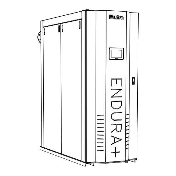
Endura+ (EDR+)
Condensing Hydronic Boilers
2,500,000 - 6,000,000 BTU/HR
UNLESS OTHERWISE NOTED
This design and drawings
DRAWN BY:
MECH. ENG:
The items shown in this
DIMENSIONS ARE IN INCHES
B. PALMER
are proprietary and are the
4/11/2016
TOLERANCES
drawing may be covered by
exclusive property of
FRACTION &
1/8
one or more patents of
WHOLE VALUE
Fulton Group N.A., Inc.
Fulton Group N.A., Inc.
CHECKED BY:
ELEC. ENG:
(1) PLACE DEC.
0.03
(2) PLACE DEC.
0.015
The corporation does not
(3) PLACE DEC.
0.005
permit their use except
ANGLE
0.5 DEG
with prior written consent.
SURFACE FINISH
B.O.M. REVIEW
APPROVED BY:
250 MICRO-INCHES
THIRD ANGLE PROJECTION
K.D.B.
4/19/2016
1 OF 1
EDRP-IOM-2024-0730
JOB NUMBER:
DESCRIPTION:
ENDURA+ CUSTOM ISO
PROJECT NAME:
PROJECT MANAGER:
Advertisement

Summary of Contents for Fulton Hogan Endura+
- Page 1 INSTALLATION, OPERATION, AND MAINTENANCE MANUAL Endura+ (EDR+) Condensing Hydronic Boilers 2,500,000 - 6,000,000 BTU/HR Serial/ National UNLESS OTHERWISE NOTED This design and drawings DRAWN BY: MECH. ENG: JOB NUMBER: DESCRIPTION: The items shown in this DIMENSIONS ARE IN INCHES ENDURA+ CUSTOM ISO B.
- Page 3 TABLE OF CONTENTS EDRP-IOM-2024-0730 Introduction Operation Overview ......................1-2 Perform Pre-Start-Up Inspection ................. 3-2 Warnings & Cautions .................... 1-2 Fill and Purge the System..................3-2 Regulatory and Standards Conformity ..............1-2 Commission The Boiler ..................3-3 SYSTEM DESIGN AND BOILER OPERATION .................3-3 Installation TURNDOWN ..........................3-4 Operation Modifiers ...................
- Page 4 TABLE OF CONTENTS EDRP-IOM-2024-0730 Service Documents Pre-Commissioning Installation Checklist ............5-3 Installation & Operation Report ................5-5 Annual Maintenance Report(s)................5-7 Notes ........................5-17 © Fulton Group N.A., 2024...
- Page 5 INTRODUCTION INTRODUCTION INSTALLATION OPERATION MAINTENANCE SERVICE DOCUMENTS Questions? Please Contact Your Local Manufacturer’s Representative...
- Page 6 INTRODUCTION SECTION 1 EDRP-IOM-2024-0730 Overview Warnings & Cautions WARNINGS and CAUTIONS appear in various chapters of this Prior to shipment, the following inspections and tests are manual. It is critical that all personnel read and adhere to all completed to ensure the highest standards of quality: information contained in WARNINGS and CAUTIONS.
- Page 7 INSTALLATION INTRODUCTION INSTALLATION OPERATION MAINTENANCE SERVICE DOCUMENTS Questions? Please Contact Your Local Manufacturer’s Representative...
- Page 8 INSTALLATION SECTION 2 EDRP-IOM-2024-0730 WARNING Product Overview All information in this manual is for Prior to the performance of installation, operation, or maintenance procedures, reference and guidance purposes, personnel should become familiar with the equipment (Table 1 and Figure 1) and and does not substitute for required its components.
- Page 9 INSTALLATION SECTION 2 EDRP-IOM-2024-0730 Placement & Rigging WARNING All information in this manual is for Proper placement of your Fulton product is essential. Attention paid to reference and guidance purposes, the following points will save a great deal of difficulty in the future. Correct and does not substitute for required placement is the first step to trouble-free installation, operation, and professional training, conduct,...
- Page 10 INSTALLATION SECTION 2 EDRP-IOM-2024-0415 TABLE 1 - BOILER DIMENSIONS AND OPERATING REQUIREMENTS Specifications EDR+ 2500 3000 4000 5000 6000 Rated Input Capacity 2,500 3,000 4,000 5,000 6,000 Minimum Input at Low Fire Output at BTS-2000 conditions 2,420 2,889 3,784 4,725 5,754 Fuel Consumption at Capacity2 SCFH...
- Page 11 INSTALLATION SECTION 2 EDRP-IOM-2024-0415 Clearances and Serviceability TABLE 2 (CONT.) - SAFETY RELIEF VALVE INLET AND OUTLET SIZES Model Trim Pressure Inlet Size Outlet Size PSI (kPa) inch (mm) inch (mm) Adhere to the following for clearances and serviceability: EDR+ 4000 30 (206.84) 2 (50.8) 2 1/2 (63.5)
- Page 12 INSTALLATION SECTION 2 EDRP-IOM-2024-0730 WARNING Install Water Piping All information in this manual is for All water supplies contain some solids, dissolved gases or dissolved minerals. reference and guidance purposes, These may cause corrosion, deposition and/or fouling of equipment. To prevent and does not substitute for required professional training, conduct, these contaminants from impacting boiler performance, valve operation and...
- Page 13 INSTALLATION SECTION 2 EDRP-IOM-2024-0730 WARNING ƒ Boiler connection dimensions are for reference and not for construction purposes. Pre-fabricating boiler piping is not recommended. All information in this manual is for reference and guidance purposes, ƒ Install filtration in the common loop or per boiler to remove particulates. A and does not substitute for required #4 or finer mesh size is required.
- Page 14 INSTALLATION SECTION 2 EDRP-IOM-2024-0415 VARIABLE SPEED FULTON ENDURA+ SYSTEM PUMP CONDENSING BOILER REMOVAL HEATING HOT WATER SUPPLY EXPANSION TANK HEATING HOT WATER RETURN UNLESS OTHERWISE NOTED This design and drawings DRAWN BY: MECH. ENG: JOB NUMBER: DESCRIPTION: The items shown in this ENDURA+ BOILER PRIMARY ONLY VARIABLE DIMENSIONS ARE IN INCHES are proprietary and are the...
- Page 15 INSTALLATION SECTION 2 EDRP-IOM-2024-0415 SYSTEM FULTON ENDURA+ (SECONDARY) CONDENSING BOILER PUMP REMOVAL SUPPLY WATER TEMPERATURE SENSOR HEATING HOT WATER SUPPLY CLOSELY SPACED TEES ( <4 x DIAMETER) DEDICATED BOILER (PRIMARY) PUMP EXPANSION TANK HEATING HOT WATER RETURN FIGURE 6 - SAMPLE PIPING LAYOUT, PRIMARY - SECONDARY PIPING; SINGLE BOILER UNLESS OTHERWISE NOTED This design and drawings DRAWN BY:...
- Page 16 INSTALLATION SECTION 2 EDRP-IOM-2024-0730 WARNING ƒ Install a motorized isolation valve per boiler. This eliminates flow through idle boilers in accordance with ASHRAE 90.1-2013 (6.5.4.3.2). Blending All information in this manual is for of unheated supply water impacts temperature control and can cause reference and guidance purposes, manual reset high temperature lockouts.
- Page 17 INSTALLATION SECTION 2 EDRP-IOM-2024-0730 Meet Water Chemistry Requirements WARNING All information in this manual is for reference and guidance purposes, System water chemistry requirements are as follows: and does not substitute for required ƒ pH: Range of 8.5 - 10.5 professional training, conduct, and strict adherence to applicable ƒ...
- Page 18 INSTALLATION SECTION 2 EDRP-IOM-2024-0415 ƒ Prevent Oxygen Contamination The gas train (see Figure 8) pressure requirements are detailed in Table 1 and on the boiler name plate located at the rear of the There are several ways to prevent boiler water oxygen boiler.
- Page 19 INSTALLATION SECTION 2 EDRP-IOM-2024-0415 ƒ Line Gas Pressure Regulation a recommended minimum of 10 total linear feet of pipe from boiler fuel train inlet. Consult the regulator When inlet gas pressure exceeds the maximum on the boiler manufacturer for installation requirements. name plate, a line gas pressure regulator is required to step the The body size should never be larger than the pipe size.
- Page 20 INSTALLATION SECTION 2 EDRP-IOM-2024-0415 4. When making gas-piping joints, use a sealing 9. After completing pressure testing and obtaining any compound resistant to the fuel gas serving the boiler. necessary approvals from the AHJ, introduce gas service and purge gas piping in accordance with local codes. 5.
- Page 21 INSTALLATION SECTION 2 EDRP-IOM-2024-0415 ƒ Multiple Boiler Installation When gas supply pressure exceeds the maximum on the boiler name plate, a line gas pressure regulator is required. It is recommended that an individual regulator be used at each boiler. See Figure 10. When a single regulator is used for multiple boilers, the regulator must be appropriate for the entire gas delivery flow (CFH) turndown range.
- Page 22 INSTALLATION SECTION 2 EDRP-IOM-2024-0415 ƒ Components Requiring Ventilation to the 2. The 1 inch (25.4 mm) boiler condensate drain outlet will be reduced and connected to the 3/4 inch (19.05 mm) Outdoors inlet on the top of the drain trap. –...
- Page 23 INSTALLATION SECTION 2 EDRP-IOM-2024-0415 Figure Notes: 1. Pipe must be slightly pitched toward the drain. 2. Pipe material must be CPVC, high-temperature silicone tubing, galvanized steel, or stainless steel. 3. The condensate drain trap outlet must be below the condensate outlet of the boiler. 4.
- Page 24 INSTALLATION SECTION 2 EDRP-IOM-2024-0415 HOUSEKEEPING PAD MINIMUM 4-INCH (102 MM) FLEXIBLE, DRAIN HOSE (SUPPLIED, REQUIRED) TRAP MUST BE FLOOR LEVEL, DO NOT ELEVATE NOTE: A ¼" FRESH WATER MAKEUP LINE IS REQUIRED. HEADER MUST BE AT FLOOR (NOT PAD) HEIGHT Figure Notes: ¼"...
- Page 25 INSTALLATION SECTION 2 EDRP-IOM-2024-0415 condensate (collecting tank and pump are not supplied 10. Ensure condensate drain piping will not be exposed to with the boiler.) freezing temperatures. 6. All piping (Figure 12) must be CPVC, high-temperature Install pH Neutralization Kit silicone tubing, galvanized, or stainless steel, and be free of leaks.
- Page 26 INSTALLATION SECTION 2 EDRP-IOM-2024-0415 TOP VIEW TANK COVER REMOVED FOR CLARITY 16 ½" 12½" 3" ISOMETRIC VIEW 1½" N.P.T. OUTLET 11⅜" 1½" N.P.T. INLET 6½" 2¾" 2¾" LEFT VIEW FRONT VIEW RIGHT VIEW FIGURE 15 - FULTON PH NEUTRALIZING KIT SINGLE BOILER MULTIPLE BOILER ASSEMBLY...
- Page 27 INSTALLATION SECTION 2 EDRP-IOM-2024-0730 WARNING Venting Requirements All information in this manual is for reference and guidance purposes, Adhere to the following venting requirements: and does not substitute for required professional training, conduct, and strict 1. This boiler can operate to the combined intake and flue exhaust pressure adherence to applicable jurisdictional/ drops without altering standard capacities: See Table 4.
- Page 28 INSTALLATION SECTION 2 EDRP-IOM-2024-0730 WARNING that cannot be captured by a pressure drop calculation such as local code requirements, accessibility for inspection and maintenance, aesthetic concerns, flue gas recirculation, stagnant vapor plumes, prevailing wind Do not terminate venting into an direction, nearby mechanical equipment and other design considerations enclosed area.
- Page 29 INSTALLATION SECTION 2 EDRP-IOM-2024-0730 WARNING TABLE 5 - PRODUCTS/CONTAMINANTS TO AVOID All information in this manual is for Products to Products containing chloro/flourocarbons; chlorine- reference and guidance purposes, avoid based products; calcium chloride products, sodium and does not substitute for required chloride products, paint and varnish removers, professional training, conduct, and strict hydrochloric acid, muriatic acid, cements, glues, antistatic...
- Page 30 INSTALLATION SECTION 2 EDRP-IOM-2024-0730 WARNING 5. For multiple boiler installations, multiply the number of boilers by required net free area per boiler. All information in this manual is for reference and guidance purposes, 6. The net free area required for the boiler(s) is in addition to the combustion and does not substitute for required or ventilation air supply requirements of other equipment sharing the professional training, conduct, and strict...
- Page 31 INSTALLATION SECTION 2 EDRP-IOM-2024-0730 WARNING 10. Avoid sidewall exhaust with roof-terminated intake air. This may lead to reverse stack effect when the boiler is idle. Fulton accepts no liability for installation of any venting, including the selection of Combustion Air Filter venting materials.
- Page 32 INSTALLATION SECTION 2 EDRP-IOM-2024-0415 TABLE 7 - FULTON APPROVED FLUE GAS VENTING ADAPTERS* Manufacturer Material Part/Catalog Number EDR+2500/3000 EDR+4000 EDR+5000/6000 Centrotherm Polypropylene ISAEDRST08 DuraVent® 810013180 (2-35-001655) or 810013437 (2-35-001656-31) or 810013438 (2-35-001654) or AL29-4C (Security) 810014740(2-35-001855) 81004279 (2-35-001857) 810014480 (2-35-001857) Enervex®...
- Page 33 INSTALLATION SECTION 2 EDRP-IOM-2024-0730 10. Horizontal vents must allow for flue gas condensate to drain back to the WARNING boiler exhaust connection with a minimum pitch of ¼” (7 mm) per foot (300 mm) run. Failure to do so can create a condensate pocket, which can All information in this manual is for result in an inoperative boiler.
- Page 34 INSTALLATION SECTION 2 EDRP-IOM-2024-0415 SEE NOTES 4, 5, 6 FULTON ENDURA+ CONDENSING BOILER SEE NOTE 8 SEE NOTE 7 REAR VIEW Figure 17 Notes: 1. All installations must be in compliance with local and national codes. This is a typical arrangement for reference SEE NOTES 4, 5, 6 purposes only.
- Page 35 INSTALLATION SECTION 2 EDRP-IOM-2024-0415 8. Consider the natural draft effects associated with 3. To prevent the possible re-circulation of flue gases, the vent designer must take into consideration such vertical exhaust vent rise. Over-draft control accessories, things as prevailing winds, eddy zones, building such as modulating stainless steel dampers, may be configurations, etc.
- Page 36 INSTALLATION SECTION 2 EDRP-IOM-2024-0415 FLUE GAS EXHAUST TERMINATION (RAIN CAP NOT REQUIRED) MIN 4 FT (122 CM) EXHAUST STACK IS DOWNWIND STORM COLLAR OF AIR INTAKE OPENING (FOR DOUBLE WALL) CAUTION: SEPARATE AIR INTAKE AND EXHAUST TERMINATIONS AS FAR AS POSSIBLE TO PREVENT FLUE GAS RECIRCULATION (FGR) DURING DIFFERENT WIND CONDITIONS.
- Page 37 INSTALLATION SECTION 2 EDRP-IOM-2024-0415 FLUE GAS EXHAUST TERMINATION (RAIN CAP NOT REQUIRED) STORM COLLAR (FOR DOUBLE WALL) TYPICAL ROOF PENETRATION COMBUSTION AIR FROM THE ROOM ( SUGGESTED INSTALLATION CONFIGURATIONS ) NOTES: 1) HORIZONTAL SECTIONS MUST ADHERE TO A MINIMUM 1/4 INCH PER FOOT (1 MM PER 48 MM) RISE TO RUN RATIO 2) MAINTAIN A MINIMUM 9 INCH (229 MM) AIR SPACE CLEARANCE TO COMBUSTABLES, WIRE, AND INSULATION 3) INSTALL SUPPORT STRAPS AT 5 FT (152 CM) HORIZONTAL...
- Page 38 INSTALLATION SECTION 2 EDRP-IOM-2024-0415 TYPICAL SIDE WALL PENETRATIONS ( SUGGESTED INSTALLATION CONFIGURATIONS ) WALL TERMINATIONS DETAIL VIEW NOTES: FLUE GAS EXHAUST TERMINATION 1) HORIZONTAL SECTIONS MUST ADHERE TO A MINIMUM 1/4 INCH PER FOOT (1 MM PER 48 MM) RISE TO RUN RATIO 2) MAINTAIN A MINIMUM 9 INCH (229 MM) AIR SPACE CLEARANCE TO COMBUSTABLES, WIRE, AND INSULATION EXHAUST STACK IS DOWNWIND...
- Page 39 INSTALLATION SECTION 2 EDRP-IOM-2024-0730 WARNING SCREW OR BOLT EACH THIMBLE COLLAR TO WALL (TYPICAL 4 PLACES) ORIENT CLAMPS AND COLLAR AS REQUIRED PIPE RETAINING All information in this manual is for CLAMP, TYPICAL EACH SIDE reference and guidance purposes, END VIEW and does not substitute for required professional training, conduct, and strict 3½...
- Page 40 INSTALLATION SECTION 2 EDRP-IOM-2024-0730 WARNING 3. The termination of the vent system must be at least 12 inches (30.48 cm) above the finished grade, or at least 12 inches (30.48 cm) above normal All information in this manual is for snow accumulation level (for applicable geographical areas).
- Page 41 INSTALLATION SECTION 2 EDRP-IOM-2024-0730 WARNING 5. Test for spillage at the draft hood relief opening after 5 minutes of main burner operation. Do not use the flame of a match or candle or smoke All information in this manual is for from a cigarette, cigar or pipe.
- Page 42 INSTALLATION SECTION 2 EDRP-IOM-2024-0730 WARNING 8. Locate the supplied wiring for the equipment and pull wiring through the appropriate conduit runs. Electrical wires are labeled for easy landing. Connect all wiring per the Fulton supplied electrical drawings. All information in this manual is for reference and guidance purposes, 9.
- Page 43 INSTALLATION SECTION 2 EDRP-IOM-2024-0730 Electrical Connections and Devices WARNING All information in this manual is for – NOTE: This boiler is factory configured for site voltage and is not intended for field reference and guidance purposes, conversion. See data plate on rear of boiler cabinet for rating. and does not substitute for required professional training, conduct, and strict The boiler is designed to operate within the following limits at the connection...
- Page 44 INSTALLATION SECTION 2 EDRP-IOM-2024-0415 REFERENCE FIELD ELECTRICAL CONNECTIONS 2-38 © Fulton Group N.A., Inc. 2024...
- Page 45 INSTALLATION SECTION 2 EDRP-IOM-2024-0415 LWCO RELAY CONTROLS STEP-DOWN TRANSFORMER SIGNAL INTERFACE BOARD (SIB) TRANSFORMER FUSES EXPANSION DC POWER MODULES SUPPLIES BLOWER FUSES BLOWER BURNER MANAGEMENT Note: Installer connections shown below are located on reverse side INSTALLER FIELD LEAD/LAG CONNECTIONS CONNECTION FIGURE 23 - EDR+2500/3000 ELECTRICAL CONTROLS LAYOUT 2-39 Questions? Please Contact Your Local Manufacturer’s Representative...
- Page 46 INSTALLATION SECTION 2 EDRP-IOM-2024-0415 LEAD/LAG BURNER CONNECTION MANAGEMENT EXPANSION INSTALLER MODULES CONNECTIONS DC POWER SUPPLIES SIGNAL INTERFACE BOARD (SIB) HIGH LWCO CONDENSATE INSTALLER RELAY CONNECTIONS RELAY CONTROLS STEP-DOWN TRANSFORMER BLOWER BLOWER FUSES TRANSFORMER FUSES FIGURE 24 - EDR+4000-6000 ELECTRICAL CONTROLS LAYOUT 2-40 ©...
- Page 47 INSTALLATION SECTION 2 EDRP-IOM-2024-0415 ƒ Junction Box Locations for Field Wiring 3. The supply header temperature sensor must be utilized. Wire the sensor to a boiler "header RTD supply" Connections (Figure 25) are provided for routing field wiring connection and install downstream of the boilers in the to the boiler control panel.
- Page 48 INSTALLATION SECTION 2 EDRP-IOM-2024-0415 ` SUPPLY HEADER TEMPERATURE SENSOR ` MOTORIZED ISOLATION VALVE CONTROL 1. A control relay is provided in the boiler control panel to 1. A field-installed hydronic supply sensor and ” NPT operate a two-position motorized isolation valve. The well are used for temperature control.
- Page 49 INSTALLATION SECTION 2 EDRP-IOM-2024-0415 3. The pump contact has a maximum rating of 6 Amps at ` AUXILIARY (2ND) LOW WATER CUTOFF 120 VAC. 1. This hydronic boiler includes one factory installed low water cut off (LWCO) device in compliance with CSD-1. 4.
- Page 50 INSTALLATION SECTION 2 EDRP-IOM-2024-0415 ` BOILER STATUS CONTACT A dry contact is provided for remote monitoring of boiler status. When the main gas valve is enabled, the contact is closed. ` BOILER DEMAND CONTACT A dry contact is provided for remote monitoring of boiler demand.
- Page 51 OPERATION INTRODUCTION INSTALLATION OPERATION MAINTENANCE SERVICE DOCUMENTS Questions? Please Contact Your Local Manufacturer’s Representative...
- Page 52 OPERATION SECTION 3 EDRP-IOM-2024-0730 WARNING Perform Pre-Start-Up Inspection All information in this manual is for Prior to start-up, perform the following: reference and guidance purposes, and does not substitute for required 1. If you smell gas: professional training, conduct, and strict adherence to applicable ƒ...
- Page 53 OPERATION SECTION 3 EDRP-IOM-2024-0730 WARNING 7. Visually inspect all pipe joints and equipment connections for leaks. If necessary, drain system, repair leaks and refill/purge the system. If no pressure drop is detected for a period of two hours under pressure, the Do not attempt to start the boiler for system may be considered watertight.
- Page 54 OPERATION SECTION 3 EDRP-IOM-2024-0730 WARNING 5. Performance factors affected may include but are not limited to input/ output ratings, efficiency, modulation rates and emissions. Non-Fulton product information is for 6. The Fulton factory Test Fire Report should be used as a point of reference reference purposes only.
- Page 55 OPERATION SECTION 3 EDRP-IOM-2024-0730 FIGURE 27 - SIEMENS AZL DISPLAY Questions? Please Contact Your Local Manufacturer’s Representative...
- Page 56 OPERATION SECTION 3 EDRP-IOM-2024-0730 ƒ Before Modifying LMV Parameters The boiler must be placed in “Commissioning Mode” before modifying any LMV parameters. Set-up must be fully completed prior to automatic operation of the boiler. ƒ Steps to Enter Parameters 1) Press and hold the “F” and “A” buttons simultaneously. a.
- Page 57 OPERATION SECTION 3 EDRP-IOM-2024-0730 1) Confirm position of the fuel selection switch where applicable. 2) Enter the password and parameter “400” will flash. 3) Press the enter (i/reset) button 2 times. a. “P1” will flash and the curve point will be displayed. –...
- Page 58 OPERATION SECTION 3 EDRP-IOM-2024-0730 ƒ Manual Firing Rate Control (Manual Request for Output) 1) Burner is in operation mode. a. The display shows oP: on the left, the percentage of the current output on the right. 2) Press and Hold the F button for 1 second. a.
- Page 59 OPERATION SECTION 3 EDRP-IOM-2024-0730 ƒ Parameter Backup 1. Press and hold “F” and “A” until Code is displayed. a. Then enter unit national board number press enter once complete. 2. “400: Set” will be displayed a. Press the”-“arrow three times until “000: Int” is displayed.
- Page 60 OPERATION SECTION 3 EDRP-IOM-2024-0730 ƒ Parameter Restore 1. Press and hold “F and A” until Code is displayed a. Then enter unit national board number press enter once complete. 2. “400: Set” will be displayed a. Press the “-“arrow two times until “100: PArA” is displayed.
- Page 61 OPERATION SECTION 3 EDRP-IOM-2024-0730 WARNING All information in this manual is for reference and guidance purposes, and does not substitute for required professional training, conduct, and strict adherence to applicable jurisdictional/professional codes and regulations. Non-Fulton product information is for reference purposes only. No Fulton document should substitute for full review of documentation available from the component manufacturer.
- Page 62 OPERATION SECTION 3 EDRP-IOM-2024-0730 WARNING Using the PURE Control® Interface All information in this manual is for Reference the PURE Control® User Manual for detailed instuctions on the reference and guidance purposes, controls system. The boiler control system features an integrated color and does not substitute for required touchscreen display through which many commissioning and operation tasks professional training, conduct,...
- Page 63 OPERATION SECTION 3 EDRP-IOM-2024-0730 WARNING A listing and functional description of each of the graphical icons found witrhin the touchscreen menus is provided below in Table 8. All information in this manual is for reference and guidance purposes, TABLE 8 - GRAPHICAL ICON REFERENCE MENU and does not substitute for required Button Function...
- Page 64 OPERATION SECTION 3 EDRP-IOM-2024-0730 WARNING PURE Control® Menu Screen Functions All information in this manual is for reference and guidance purposes, ƒ Boiler Control and does not substitute for required professional training, conduct, General individual boiler and ancillary functionality is accessed through this and strict adherence to applicable category.
- Page 65 OPERATION SECTION 3 EDRP-IOM-2024-0730 WARNING When in Automatic Control, the temperature controller will modulate the burner to a firing rate necessary to achieve the setpoint. To enter Manual Control, tap the “Automatic Control” button, and it will change to “Manual All information in this manual is for Control.
- Page 66 OPERATION SECTION 3 EDRP-IOM-2024-0730 WARNING ` SECONDARY PUMPS This screen will only be accessible if Secondary Pumps is selected. See Auxiliary All information in this manual is for Configuration. reference and guidance purposes, and does not substitute for required Pumps may be configured to maintain either system delta-P or delta-T. Rotation professional training, conduct, is automatic.
- Page 67 OPERATION SECTION 3 EDRP-IOM-2024-0730 WARNING ƒ PID Control All information in this manual is for Local PID and firing rate modifiers are accessed in this category. reference and guidance purposes, and does not substitute for required ` LOCAL PID professional training, conduct, and strict adherence to applicable Use the slider to set how passive or aggressive the control will act to meet jurisdictional/professional codes...
- Page 68 OPERATION SECTION 3 EDRP-IOM-2024-0730 WARNING ƒ Setpoint The boiler or multiple boiler system will maintain supply water temperature All information in this manual is for reference and guidance purposes, based on a setpoint temperature. This setpoint can come from a variety of and does not substitute for required sources, including by calculation from an outdoor air temperature sensor, a professional training, conduct,...
- Page 69 OPERATION SECTION 3 EDRP-IOM-2024-0730 WARNING ƒ Admin Administrative functions are used during initial commissioning, troubleshooting All information in this manual is for reference and guidance purposes, and other advanced tasks. and does not substitute for required professional training, conduct, ` SYSTEM CONFIGURATION and strict adherence to applicable jurisdictional/professional codes The System Configuration screen is used for saving (backup) and loading of...
- Page 70 OPERATION SECTION 3 EDRP-IOM-2024-0730 WARNING Commissioning Mode All information in this manual is for The boiler must be placed in commissioning mode prior to adjusting combus- reference and guidance purposes, tion parameters. This screen is intended for trained factory authorized techni- and does not substitute for required cians.
- Page 71 MAINTENANCE INTRODUCTION INSTALLATION OPERATION MAINTENANCE SERVICE DOCUMENTS Questions? Please Contact Your Local Manufacturer’s Representative...
- Page 72 MAINTENANCE SECTION 4 EDRP-IOM-2024-0730 WARNING General All information in this manual is for This boiler has been designed to provide years of trouble free performance. reference and guidance purposes, To ensure continued safety and efficiency of the boiler, please follow the and does not substitute for required maintenance and inspection directions outlined in this section of the manual.
- Page 73 MAINTENANCE SECTION 4 EDRP-IOM-2024-0730 Tool List WARNING All information in this manual is for To complete routine preventative maintenance or repairs, certain tools and reference and guidance purposes, supplies will be required that are not provided with the boiler. The qualified and does not substitute for required service technician should be prepared with the following tools and supplies.
- Page 74 MAINTENANCE SECTION 4 EDRP-IOM-2024-0730 WARNING Monthly Maintenance Schedule Personnel performing burner Monthly maintenance and inspection must include the following: assembly maintenance must wear appropriate respiratory protection. 1. Test high-limit control by reducing setting below the operating Failure to do so may result in the temperature;...
- Page 75 MAINTENANCE SECTION 4 EDRP-IOM-2024-0730 Annual Maintenance Schedule WARNING All information in this manual is for Annual maintenance and inspection must be performed prior to each heating reference and guidance purposes, season, and includes but is not limited to the following tasks, which must be and does not substitute for required done by a factory trained technician: professional training, conduct,...
- Page 76 MAINTENANCE SECTION 4 EDRP-IOM-2024-0730 Removing, Inspecting and Cleaning Burner WARNING THE O2 COMPENSATION READOUT For the following procedure, be sure to reference Figures 28 and 29. IS NOT A REPLACEMENT FOR A CALIBRATED FLUE GAS ANALYZER. 1. Remove power and turn off gas supply. Allow the boiler to cool. Under no circumstances should the O2 compensation readout value be 2.
- Page 77 MAINTENANCE SECTION 4 EDRP-IOM-2024-0730 10. Carefully reinstall the burner: Replace both burner gaskets, do not reuse WARNING the burner gaskets. Apply C5-A Antiseize (PN 2-12-000191) to threads, and reinstall the burner flange washers and nuts using only originally supplied Specified torque values are mandatory or genuine Fulton replacement hardware.
- Page 78 MAINTENANCE SECTION 4 EDRP-IOM-2024-0730 Inspecting the Pilot Ignition Assembly WARNING THE O2 COMPENSATION READOUT IS NOT A REPLACEMENT FOR A – NOTE: This section applies only to Endura+ boilers equipped with a pilot ignition. CALIBRATED FLUE GAS ANALYZER. The pilot assembly requires annual inspection; although it is considered a wear- Under no circumstances should the item it is not intended to be replaced on an annual basis.
- Page 79 MAINTENANCE SECTION 4 EDRP-IOM-2024-0730 BILL OF MATERIAL ITEM PART NUMBER DESCRIPTION U.O.M. 2-12-315004 1/8"ID x 1/4"OD ABRASION RESISTANT, FLEXIBLE NEOPRENE TUBING 2-20-000023 3" WATER LEVEL PROBE 2-22-002600 10-24 UNC X 1" CROSS PAN HEAD MACHINE SCREW 2-22-315031 2- 54 UNC X 3/4" CROSS PAN HEAD MACHINE SCREW, ZINC-PLATED 2-22-315032 2-56 STOP NUT - NYLON INSERT - STEEL, ZINC PLATED...
- Page 80 MAINTENANCE SECTION 4 EDRP-IOM-2024-0730 BILL OF MATERIAL BILL OF MATERIAL ITEM PART NUMBER DESCRIPTION U.O.M. ITEM PART NUMBER DESCRIPTION U.O.M. 2-12-315004 1/8"ID x 1/4"OD ABRASION RESISTANT, FLEXIBLE NEOPRENE 2-40-000251 OPERATING LIMIT AQUASTAT (100-240F) TUBING 2-40-000294 HIGH LIMIT AQUASTAT WITH MANUAL RESET (100-200F) 2-20-000023 3"...
- Page 81 MAINTENANCE SECTION 4 EDRP-IOM-2024-0730 BILL OF MATERIAL BILL OF MATERIAL ITEM PART NUMBER DESCRIPTION U.O.M. ITEM PART NUMBER DESCRIPTION U.O.M. 2-10-000219 3/8" x .035" WALL SS316 TUBING 2-35-000296 1 1/2" 150# CARBON STEEL UNION 2-30-000003 1 1/2" N.P.T.GAS VALVE VGG10.404U 2-35-000371 1/4"...
- Page 82 MAINTENANCE SECTION 4 EDRP-IOM-2024-0730 BILL OF MATERIAL BILL OF MATERIAL ITEM PART NUMBER DESCRIPTION U.O.M. ITEM PART NUMBER DESCRIPTION U.O.M. 2-10-000219 3/8" x 0.035" WALL SS316 TUBING 2-35-000289 2" 150# THREADED CAP 2-30-000004 2" N.P.T. GAS VALVE VGG10.504U (15 PSI MAX) 2-35-000294 2"...
- Page 83 MAINTENANCE SECTION 4 EDRP-IOM-2024-0730 BILL OF MATERIAL BILL OF MATERIAL ITEM PART NUMBER DESCRIPTION U.O.M. ITEM PART NUMBER DESCRIPTION U.O.M. 2-10-000219 3/8" x 0.035" WALL SS316 TUBING 2-35-000306 1/4" 3000# PLUG 2-30-000298 1/2" AUTOMATIC PILOT GAS VALVE (120/60) 2-35-000370 1/2" X 9" - NPT SCH 40 NIPPLE CSA/UL/FM (8214G020) 5 PSI MAX 2-35-000371 1/4"...
- Page 84 MAINTENANCE SECTION 4 EDRP-IOM-2024-0730 BILL OF MATERIAL BILL OF MATERIAL ITEM PART NUMBER DESCRIPTION U.O.M. ITEM PART NUMBER DESCRIPTION U.O.M. 2-40-000474 SIEMENS LMV3 PLUG CONNECTION SET (AGG3.131) 2-45-000809 SINGLE CIRCUIT, 65A TERMINAL BLOCK (18GA. - 6GA.) 2-40-000476 LMV36.520A1 120V SINGLE FUEL BURNER CONTROL 2-45-000810 DIN RAIL END ANCHOR (35MM) *PROGRAMMING BY FULTON*...
- Page 85 MAINTENANCE SECTION 4 EDRP-IOM-2024-0730 BILL OF MATERIAL BILL OF MATERIAL ITEM PART NUMBER DESCRIPTION U.O.M. ITEM PART NUMBER DESCRIPTION U.O.M. 2-40-000474 SIEMENS LMV3 PLUG CONNECTION SET (AGG3.131) 2-45-000813 SINGLE CIRCUIT GROUND TERMINAL BLOCK (22GA. - 2-40-000476 LMV36.520A1 120V SINGLE FUEL BURNER CONTROL 8GA.) 2-40-001421 FULTON HI/LO WATER RELAY...
- Page 86 MAINTENANCE SECTION 4 EDRP-IOM-2024-0730 BILL OF MATERIAL BILL OF MATERIAL ITEM PART NUMBER DESCRIPTION U.O.M. ITEM PART NUMBER DESCRIPTION U.O.M. 2-22-315003 TIGHT SEAL STAINLESS STEEL BOLT CLAMP WITH ZINC 2-12-315002 FLEXIBLE COUPLING (SIZE 4, NEOPENE FOR NG / PLATE STEEL SCREW NITRILE FOR PROPANE) 2-22-315022 DURABLE NYLON TIGHT-SEAL BARBED PLUG...
- Page 87 MAINTENANCE SECTION 4 EDRP-IOM-2024-0730 BILL OF MATERIAL BILL OF MATERIAL ITEM PART NUMBER DESCRIPTION U.O.M. ITEM PART NUMBER DESCRIPTION U.O.M. 2-40-315310 5.4" BORE PBA INLET BUTTERFLY AIR SERVO 2-22-315022 DURABLE NYLON TIGHT-SEAL BARBED PLUG 2-12-315002 FLEXIBLE COUPLING (SIZE 4) 2-22-315041 3/8-16 HEX NYLOC NUT, GR.
- Page 88 MAINTENANCE SECTION 4 EDRP-IOM-2024-0730 BILL OF MATERIAL BILL OF MATERIAL ITEM PART NUMBER DESCRIPTION U.O.M. ITEM PART NUMBER DESCRIPTION U.O.M. 2-12-315004 1/8"ID x 1/4"OD ABRASION RESISTANT, 2-22-315041 3/8-16 HEX NYLOC NUT, GR. 5 FLEXIBLE NEOPRENE TUBING 2-22-315045 TIGHT SEAL STAINLESS STEEL BOLT CLAMP 2-12-315012 EDR+ 6000 INLET TO BLOWER GASKET 2-30-001266...
- Page 89 MAINTENANCE SECTION 4 EDRP-IOM-2024-0730 BILL OF MATERIAL ITEM PART NUMBER DESCRIPTION U.O.M. 2-12-000012 3/4" NPT SIGHT OBSERVATION PORT 2-12-000721 029 1/16" VITON O-RING 1.625 OD 2-12-315005 EDR+ 3000 BURNER TO PV GASKET 2-12-315007 EDR+ 3000 PREMIX TO BURNER GASKET 2-22-000156 3/8-16 NiCu400 HEX NUT (MONEL400) 2-22-000353 3/8"...
- Page 90 MAINTENANCE SECTION 4 EDRP-IOM-2024-0730 BILL OF MATERIAL ITEM PART NUMBER DESCRIPTION U.O.M. 2-12-000012 3/4" NPT SIGHT OBSERVATION PORT 2-12-000721 029 1/16" VITON O-RING 1.625 OD 2-12-315011-31 EDR+4000-6000 PREMIX / FURNACE GASKET 2-22-000058 1/2-13 HEX NUT, GR. 2H 2-22-315039 1/2" BELLEVILLE WASHER (SS301, 0.519"ID x 1.24"OD x 0.125"THK) 2-22-315040 1/4-20 X 3/4"...
- Page 91 MAINTENANCE SECTION 4 EDRP-IOM-2024-0730 Troubleshooting Use the following tables as a guide to troubleshooting your boiler. PROBLEM CAUSE CHECK Boiler Will Not Start Controller/Settings Check for active alarms. Investigate and address root cause and reset as necessary. Navigate to the Boiler Status screen from the Boiler Control menu. Check the following: y Boiler Status at the top of the screen.
- Page 92 MAINTENANCE SECTION 4 EDRP-IOM-2024-0730 PROBLEM CAUSE CHECK No Power to Controls Electrical/Wiring Check fusing and replace as necessary. Measure incoming voltage to boiler is in compliance with requirements and stepdown transformer output is 120VAC. Verify control power supply voltage at PS1 (24 VDC) and PS2 (12 VDC). Verify power plugs are fastened securely to control devices.
- Page 93 MAINTENANCE SECTION 4 EDRP-IOM-2024-0730 PROBLEM CAUSE CHECK VFD Speed Error/Fault Controller/Settings Verify that the fault is being logged in the PURE Control™ alarm history. Record the code, diagnostic, phase and firing rate at which the fault(s) occurred. Check for any fault codes on the VFD. Verify that the cooling fan in the bottom of the VFD is operational.
- Page 94 MAINTENANCE SECTION 4 EDRP-IOM-2024-0730 PROBLEM CAUSE CHECK LED Illuminated on SAS Maintenance/Safeties See below for LED meaning: Actuator y Green (steady) - Automatic Mode; Normal operation y Green (blinking) - Calibration or Manual Mode; Wait until calibration has finished or manual adjuster is in MAN position y Red (steady) - Calibration error or Undervoltage (13VAC);...
- Page 95 MAINTENANCE SECTION 4 EDRP-IOM-2024-0730 PROBLEM CAUSE CHECK UV Scanner Fault/Flame Installation Verify that no sources of bright light can be picked up by the sensor through the sight Out of Sequence glass. Electrical/Wiring Verify wiring and connection between the UV scanner and the flame safeguard. Remove and visually inspect the UV scanner.
- Page 96 MAINTENANCE SECTION 4 EDRP-IOM-2024-0730 PROBLEM CAUSE CHECK No SD Card Error Controller/Settings Install/Replace SD card with a capacity of 4GB or larger. Reference Installation and Operation Manual Pure Control™ Addendum for more information on SD card. Main Flame Failure Maintenance Verify combustion parameters at all combustion points P1-P9.
- Page 97 MAINTENANCE SECTION 4 EDRP-IOM-2024-0730 PROBLEM CAUSE CHECK Burner Harmonic or Maintenance Inspect air filter, replace if dirty. Resonance Verify combustion at all operating points. Inspect burner, clean according to maintenance instructions if dirty. Proceed to resonator adjustment ONLY AFTER verifying the above. Consult factory for resonator adjustment.
- Page 98 MAINTENANCE SECTION 4 EDRP-IOM-2024-0730 THIS PAGE LEFT INTENTIONALLY BLANK 4-28 © Fulton Group N.A., Inc. 2024...
- Page 99 SERVICE DOCUMENTS INTRODUCTION INSTALLATION OPERATION MAINTENANCE SERVICE DOCUMENTS Questions? Please Contact Your Local Manufacturer’s Representative...
- Page 100 SERVICE DOCUMENTS SECTION 5 EDRP-IOM-2024-0730 PAGE INTENTIONALLY LEFT BLANK © Fulton Group N.A., 2024...
- Page 101 SERVICE DOCUMENTS SECTION 5 EDRP-IOM-2024-0730 PRE-COMMISSIONING INSTALLATION CHECKLIST NOTE: TO BE COMPLETED BY INSTALLING CONTRACTOR. DATE JOB SITE NAME CONTACT NAME PHONE NUMBER BOILER MODEL BOILER NB/SERIAL #(s) ELECTRICAL & COMMUNICATION: Electrical wiring to the boiler terminated and tested? Voltage matches the data plate on the rear of the boiler? Control wiring for lead/lag is terminated and tested? Building automation wiring is terminated and tested? SYSTEM PIPING...
- Page 102 SERVICE DOCUMENTS SECTION 5 EDRP-IOM-2024-0730 PAGE INTENTIONALLY LEFT BLANK © Fulton Group N.A., 2024...
- Page 103 SERVICE DOCUMENTS SECTION 5 EDRP-IOM-2024-0730 ENDURA+ (EDR+) INSTALLATION & OPERATION “START-UP” REPORT NOTE: TO BE COMPLETED BY A FACTORY AUTHORIZED TECHNICIAN HOLDING A VALID ENDURA+ (EDR+) CERTIFICATE OF REGISTRATION. WARRANTY COVERAGE IS VALID ONLY IF THIS FORM IS SUCCESSFULLY COMPLETED AND RETURNED TO FULTON WITHIN TWELVE WEEKS OF START-UP. DATE FULTON REP.
- Page 104 SERVICE DOCUMENTS SECTION 5 EDRP-IOM-2024-0730 CONTROLS: Boiler setpoint source (i.e. BMS, OAT, 4-20mA, Local) Is the boiler configured for internal lead/lag? Motorized isolation valve wired and functional? (Note: Variable-Primary only) Dedicated primary pump wired and functional? (Note: Primary-Secondary only) Software update performed?* Software version in use: VERSION: *Do not skip this step unless instructed by the factory.
- Page 105 SERVICE DOCUMENTS SECTION 5 EDRP-IOM-2024-0730 ENDURA+ (EDR+) ANNUAL MAINTENANCE CHECKLIST NOTE: TO BE COMPLETED BY A FACTORY AUTHORIZED TECHNICIAN HOLDING A VALID ENDURA+ (EDR+) CERTIFICATE OF REGISTRATION. DATE TECH CERTIFICATE # TECHNICIAN BOILER MODEL TECH. COMPANY BOILER NB/SERIAL # ANNUAL MAINTENANCE: Burner head removed and visually inspected COMPLETE Burner head cleaned (air only)
- Page 106 SERVICE DOCUMENTS SECTION 5 EDRP-IOM-2024-0730 COMBUSTION SETTINGS: FIRING POSITION: LIGHT 100% Fuel Position Air Position Air Position Air Position Air Position Blower Position Air Position Air Position Air Position Blower Ampere Incoming Voltage Supply Gas Pressure (InWC)* Manifold Gas Pressure (InWC)* MV Downstream Gas (InWC )* Fan Discharge Pressure (InWC)* Analyzer O2%...
- Page 107 SERVICE DOCUMENTS SECTION 5 EDRP-IOM-2024-0730 ENDURA+ (EDR+) ANNUAL MAINTENANCE CHECKLIST NOTE: TO BE COMPLETED BY A FACTORY AUTHORIZED TECHNICIAN HOLDING A VALID ENDURA+ (EDR+) CERTIFICATE OF REGISTRATION. DATE TECH CERTIFICATE # TECHNICIAN BOILER MODEL TECH. COMPANY BOILER NB/SERIAL # ANNUAL MAINTENANCE: Burner head removed and visually inspected COMPLETE Burner head cleaned (air only)
- Page 108 SERVICE DOCUMENTS SECTION 5 EDRP-IOM-2024-0730 COMBUSTION SETTINGS: FIRING POSITION: LIGHT 100% Fuel Position Air Position Air Position Air Position Air Position Blower Position Air Position Air Position Air Position Blower Ampere Incoming Voltage Supply Gas Pressure (InWC)* Manifold Gas Pressure (InWC)* MV Downstream Gas (InWC )* Fan Discharge Pressure (InWC)* Analyzer O2%...
- Page 109 SERVICE DOCUMENTS SECTION 5 EDRP-IOM-2024-0730 ENDURA+ (EDR+) ANNUAL MAINTENANCE CHECKLIST NOTE: TO BE COMPLETED BY A FACTORY AUTHORIZED TECHNICIAN HOLDING A VALID ENDURA+ (EDR+) CERTIFICATE OF REGISTRATION. DATE TECH CERTIFICATE # TECHNICIAN BOILER MODEL TECH. COMPANY BOILER NB/SERIAL # ANNUAL MAINTENANCE: Burner head removed and visually inspected COMPLETE Burner head cleaned (air only)
- Page 110 SERVICE DOCUMENTS SECTION 5 EDRP-IOM-2024-0730 COMBUSTION SETTINGS: FIRING POSITION: LIGHT 100% Fuel Position Air Position Air Position Air Position Air Position Blower Position Air Position Air Position Air Position Blower Ampere Incoming Voltage Supply Gas Pressure (InWC)* Manifold Gas Pressure (InWC)* MV Downstream Gas (InWC )* Fan Discharge Pressure (InWC)* Analyzer O2%...
- Page 111 SERVICE DOCUMENTS SECTION 5 EDRP-IOM-2024-0730 ENDURA+ (EDR+) ANNUAL MAINTENANCE CHECKLIST NOTE: TO BE COMPLETED BY A FACTORY AUTHORIZED TECHNICIAN HOLDING A VALID ENDURA+ (EDR+) CERTIFICATE OF REGISTRATION. DATE TECH CERTIFICATE # TECHNICIAN BOILER MODEL TECH. COMPANY BOILER NB/SERIAL # ANNUAL MAINTENANCE: Burner head removed and visually inspected COMPLETE Burner head cleaned (air only)
- Page 112 SERVICE DOCUMENTS SECTION 5 EDRP-IOM-2024-0730 COMBUSTION SETTINGS: FIRING POSITION: LIGHT 100% Fuel Position Air Position Air Position Air Position Air Position Blower Position Air Position Air Position Air Position Blower Ampere Incoming Voltage Supply Gas Pressure (InWC)* Manifold Gas Pressure (InWC)* MV Downstream Gas (InWC )* Fan Discharge Pressure (InWC)* Analyzer O2%...
- Page 113 SERVICE DOCUMENTS SECTION 5 EDRP-IOM-2024-0730 ENDURA+ (EDR+) ANNUAL MAINTENANCE CHECKLIST NOTE: TO BE COMPLETED BY A FACTORY AUTHORIZED TECHNICIAN HOLDING A VALID ENDURA+ (EDR+) CERTIFICATE OF REGISTRATION. DATE TECH CERTIFICATE # TECHNICIAN BOILER MODEL TECH. COMPANY BOILER NB/SERIAL # ANNUAL MAINTENANCE: Burner head removed and visually inspected COMPLETE Burner head cleaned (air only)
- Page 114 SERVICE DOCUMENTS SECTION 5 EDRP-IOM-2024-0730 COMBUSTION SETTINGS: FIRING POSITION: LIGHT 100% Fuel Position Air Position Air Position Air Position Air Position Blower Position Air Position Air Position Air Position Blower Ampere Incoming Voltage Supply Gas Pressure (InWC)* Manifold Gas Pressure (InWC)* MV Downstream Gas (InWC )* Fan Discharge Pressure (InWC)* Analyzer O2%...
- Page 115 SERVICE DOCUMENTS SECTION 5 EDRP-IOM-2024-0730 NOTES 5-17 Questions? Please Contact Your Local Manufacturer’s Representative...
- Page 116 SERVICE DOCUMENTS SECTION 5 EDRP-IOM-2024-0730 NOTES 5-18 © Fulton Group N.A., 2024...
- Page 117 SERVICE DOCUMENTS SECTION 5 EDRP-IOM-2024-0730 NOTES 5-19 Questions? Please Contact Your Local Manufacturer’s Representative...
- Page 118 No part of this Installation, Operation, and Maintenance manual may be reproduced in any form or by any means without permission in writing from Fulton Group N.A., Inc. Fulton Thermal Corporation is part of Fulton Group N.A., Inc., a global manufacturer of steam, hot water and thermal fluid heat transfer systems.
Need help?
Do you have a question about the Endura+ and is the answer not in the manual?
Questions and answers