
Related Manuals for Star LCS850MG

Summary of Contents for Star LCS850MG
- Page 1 INSTALLATION AND INSTRUCTION MANUAL LCS850MG SIREN AMPLIFIER & LIGHT CONTROLLER 455 Rochester Street Avon, NY 14414 585-226-9500 (F) 888-478-2797 www.StarSafetyTechnologies.com PLIT426 REV. H 2/1/24...
-
Page 2: Table Of Contents
Siren Wiring Diagram #1 _____ AUX Wire Label Insertion _____ Audio Pursuit 12-terminal Connector (Audio I/O) Siren Wiring Diagram #2 _____ Visual Pursuit LCS850MG-XF12 Microphone Harness _____ Progressive Slide Switch OPERATION 46-50 _____ TD Output SLIDE SWITCH _____ Auto On... -
Page 3: Overview
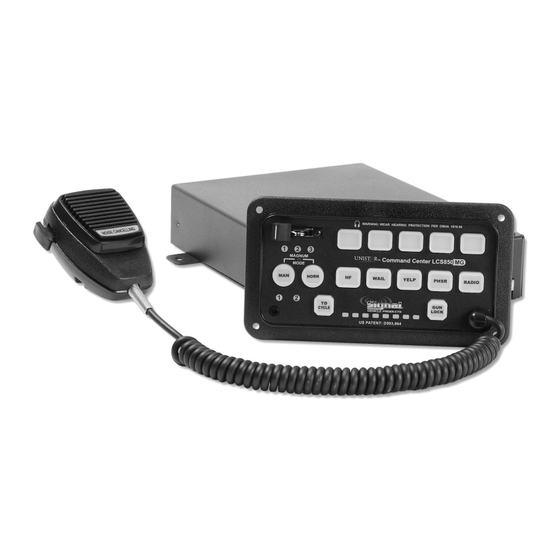
Due to continuous product improvements, we must reserve the right to change any specifications and information, contained in this manual at any time without notice. Star Safety Technologies and/or the manufacturer make no warranty of any kind with regard to this manual, including, but not limited to, the The LCS850MG Siren Amplifier is a premium 200W unit designed for dual 100W speaker implied warranties of merchantability and fitness for a particular purpose. -
Page 4: Specifications
Control Head Dip Switch Settings Overview Specifications Installation Star recommends that you bench test the unit immediately after receipt to ensure that it was Input Voltage 10 - 16 VDC (negative ground) not damaged in shipping. Then you should program all settings and test again prior to Input Current 8.0 Amps @ 13.6 VDC (single 100W speaker) - Page 5 NOTE: If the AUX wire DIP switch is set for the MANUAL function Air Horn operation of our DL15-30W. To program the LCS850MG (and the HRT is connected), neither your vehicle horn, nor to operate other traffic directors, please refer to page 32 the siren Air Horn will sound when you press your steering of the Detailed Programming section.
- Page 6 Installation: Dip Switch Settings Installation: Dip Switch Settings Control Head Dip Switch Settings Control Head Dip Switch Settings (cont’d) (cont’d) Button Auto On, Magnum Mode, and Radio Rebroadcast Phaser, Sweep, Programming Mode 11 12 13 14 PHASER ENABLE (Optional Phaser Tone or ON/OFF Switch for the PB13 output) Normally, the PHASER button is used to activate PHASER Button Controls the Phaser siren tone.
-
Page 7: Amplifier Dip Switch Settings
By default, the LCS850MG is compatible with any of our ground-side switched 8-head traffic director (e.g. TD77, TD92, TD93, etc.) and will use its own internal controller to drive the “dummy”... - Page 8 VISUAL PURSUIT on page 31). Standard Left Arrow Pattern Dual Travelling Left ArrowPattern Normally the LCS850MG will use all 8 heads as part of the traffic directing pattern. To switch to Phantom mode, move DIP switch 4 (on the far left of the first bank of DIP switches) AWAY the edge of the siren (UP).
-
Page 9: Detailed Programming Summary Table Of Contents
This section only applies to those Traffic Directors that have a built-in controller, Refer to pages 15-34 for detailed programming instructions. but will be operated with the TD CYCLE button through “signal” wires. The LCS850MG has three different “logic controlled” modes that can be used, depending Option Default Setting Optional Setting upon the input requirements of your Traffic Director. -
Page 10: Detailed Programming Legend
Installation: Detailed Programming Installation: Detailed Programming Detailed Programming Legend Placing the Siren Into Programming Mode Detailed Programming Instructions AUDIO PUSH DEFAULT MODE FUNCTION DEFINITION BUTTON SETTING BUTTON The following section gives a detailed description of how to program each of the options listed Gun Lock Buttons ALL PB ONLY PB4... - Page 11 All of the options on pages 17-34 can optionally be programmed using free software and a Button Operation (Latched or Momentary) USB to serial cable (P/N SUSB-850MG) available upon request from Star at 585-226-9787. If you would like any of the buttons to act as a “momentary” pushbutton switch instead (ON only while held in), change this setting.
- Page 12 All of the options on pages 17-34 can optionally be programmed using free software and a USB to serial cable (P/N SUSB-850MG) available upon request from Star at 585-226-9787. USB to serial cable (P/N SUSB-850MG) available upon request from Star at 585-226-9787.
- Page 13 All of the options on pages 17-34 can optionally be programmed using free software and a Steady or Flashing/Pulsed Outputs USB to serial cable (P/N SUSB-850MG) available upon request from Star at 585-226-9787. The outputs switched by each push button normally apply steady +12 VDC.
- Page 14 All of the options on pages 17-34 can optionally be programmed using free software and a Siren Disable (PA and Horn Functions only) USB to serial cable (P/N SUSB-850MG) available upon request from Star at 585-226-9787. If you desire to COMPLETELY disable the siren feature from this unit, allowing only the PA, Horn, Manual “Step-Up”...
- Page 15 HF Mode at Boot • By default, when the LCS850MG unit is powered up, no Audio Mode will be selected (active). Program each siren tone separately. If you would like the siren to automatically be in HF Mode (siren can be activated by AUX wire/HRT), •...
- Page 16 Second Tone Swap All of the options on pages 17-34 can optionally be programmed using free software and a USB to serial cable (P/N SUSB-850MG) available upon request from Star at 585-226-9787. Second Tone Swap in Magnum Mode for Slide Switch...
- Page 18 High-Low (Two-Tone) Override of Phaser Tone All of the options on pages 17-34 can optionally be programmed using free software and a USB to serial cable (P/N SUSB-850MG) available upon request from Star at 585-226-9787. Tone Sweep Disable in HF for Slide Switch •...
- Page 19 All of the options on pages 17-34 can optionally be programmed using free software and a USB to serial cable (P/N SUSB-850MG) available upon request from Star at 585-226-9787. USB to serial cable (P/N SUSB-850MG) available upon request from Star at 585-226-9787.
- Page 20 Logic Controlled Output Select As indicated on page 6, page 13, and above, the LCS850MG has the ability to operate a Traffic Director (Note: This only applies to the button or slide switch outputs, it does NOT apply to the (arrowstick) that has a built in controller (i.e.
- Page 21 All of the options on pages 17-34 can optionally be programmed using free software and a USB to serial cable (P/N SUSB-850MG) available upon request from Star at 585-226-9787. USB to serial cable (P/N SUSB-850MG) available upon request from Star at 585-226-9787.
-
Page 22: Mounting
(See diagram to " Bolt #8 Screws right). • The LCS850MG control head may be mounted above the dash, below the dash, or in a rack with the mounting u-bracket provided. 5. Adjust the control head and tighten the hardware. •... -
Page 23: Electrical Connections
Siren Amplifier and Relay Control Box Electrical Connections • The LCS850MG amplifier should be mounted in a location such as the driver compartment firewall, under the seat, or in the trunk. The following steps are recommended when installing, to help reduce RFI: •... -
Page 24: Power And Ground Connections
Installation Installation: Wiring Slide Switch and Push Button Outputs Electrical Connections (CONT’D Power and Ground Wiring Connections Slide Switch and Push Button Outputs Communications Port Slide Switch and Push Audio I/O Button Outputs CPU Serial Interface Battery Traffic Director Outputs Power Negative Electrical connections to the unit are made using several terminals and removable... -
Page 25: 10-Terminal Connector (Ss And Pushbutton Outputs)
Installation Installation: Wiring Wiring Diagram #1 12-Terminal Connector (Audio I/O) (CONT’D) 10-Terminal Connector Label Insertion Siren Wiring Diagram #1 Label Insertion Inputs and Light Outputs Once the wire connections have been made to PB1- PB5, PB13, and PB14, labels can be inserted into the switches. -
Page 26: 12-Terminal Connector (Audio I/O)
Installation: Wiring Installation 12-Terminal Connector (Audio I/O) Wiring Diagram #2 12-Terminal Connector 12-Terminal Audio Connector Inputs and Outputs (See wiring diagram on page 44) P30041-68 Terminal 1: Speaker 2 (Negative) - <BROWN> Connect to the negative terminal from your second speaker. Use a minimum 14 AWG wire. Terminal 2: Speaker 2 (Positive) - <BROWN w/WHITE>... -
Page 27: Lcs850Mg-Xf12 Microphone Harness
Operation Slide Switch and Pushbuttons LCS850MG-XF12 Microphone Harness The LCS850MG-XF12 comes with an extension harness for the microphone. Make your Operation connections as indicated below. General This unit is designed for easy operation under the stress associated with high-speed pursuit. -
Page 28: Audio Mode Buttons
Operation Operation MAN Button Audio Mode Buttons Volume Controls Audio Mode Buttons MAN and HORN Buttons The five (5) push buttons across the middle of the There are two (2) other push buttons across the middle of the control head that are used to control head are used to select the various “audio control additional audio functions, the MAN and HORN buttons. -
Page 29: Air Horn
Both Simultaneous Flashing - There is an electrical short in one of the speakers or wires Magnum Mode to the speakers. The amplifier box in the LCS850MG contains two separate Both Alternating - Incorrect voltage (<10 VDC or >16 VDC). amplifiers that allow the user to operate two separate and Both Tripleflash - Siren Disable/Audio Lockout activated (see page 24). -
Page 30: Cloning
Fuses and Parts Cloning Service The LCS850MG has been designed to allow for the settings of one unit to be “cloned” or Fuses copied to another unit, thus reducing the time that it takes to program multiple units. This feature is extremely useful when setting up fleets of vehicles that will all be using the same The outputs on this unit are protected by ten 20 Amp (or similar) options. -
Page 31: Troubleshooting
The loss of use of the product, loss of time, inconvenience, +12VDC applied to it. commercial loss or consequential damages, including costs of any labor, are not covered. Star No siren tone - PA High voltage protection The input voltage must be less than 16 volts. - Page 32 RMA number (Returned Materials Authorization Number). No returns will be allowed for product returns that are not listed on the RMA. Please fill out the form below and enclose it with the returned product(s). Returned Materials Authorization Form LCS850MG MODEL: Serial Number...
Need help?
Do you have a question about the LCS850MG and is the answer not in the manual?
Questions and answers