
Related Manuals for Datavideo HRS-30


Summary of Contents for Datavideo HRS-30
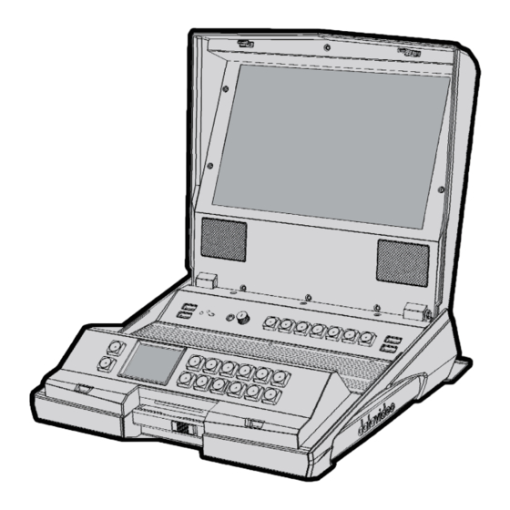
- Page 1 FIELDSIDE HAND CARRY RECORDER HRS-30 Instruction Manual w w w . d a t a v i d e o . c o m...
-
Page 2: Table Of Contents
WARNINGS AND PRECAUTIONS ................... 4 WARRANTY........................... 5 ......................5 TANDARD ARRANTY ......................6 HREE ARRANTY DISPOSAL ..........................6 UNPACKING THE HRS-30 ...................... 7 ..........................7 ..........................8 ATTERY 2.5" H ..................... 9 SSEMBLE RIVE Connect to PC ......................10 Connect to MAC ......................11 PRODUCT OVERVIEW ...................... - Page 3 Datavideo Technologies will try to give correct, complete and suitable information. However, Datavideo Technologies cannot exclude that some information in this manual, from time to time, may not be correct or may be incomplete. This manual may contain typing errors, omissions or incorrect information.
-
Page 4: Fcc Compliance Statement
AC adapter. If you are not sure of the type of power available, consult your Datavideo dealer or your local power company. 8. Do not allow anything to rest on the power cord. Do not locate this unit where the power cord will be walked on, rolled over, or otherwise stressed. -
Page 5: Warranty
Warranty Standard Warranty Datavideo equipment are guaranteed against any manufacturing defects for one year from the date of purchase. The original purchase invoice or other documentary evidence should be supplied at the time of any request for repair under warranty. -
Page 6: Three Year Warranty
Drive, Solid State Drive, SD Card, USB Thumb Drive, Lighting, Camera module, PCIe Card are covered for 1 year. The three-year warranty must be registered on Datavideo's official website or with your local Datavideo office or one of its authorized distributors within 30 days of purchase. -
Page 7: Unpacking The Hrs-30
Unpacking the HRS-30 Place the HRS-30 on a level desk or surface. The carry handle will be on the right side facing the operator’s position. To open the HRS-30 monitor lid, slide the thumb catches in the direction shown to their outer most position. -
Page 8: Battery
Battery The HRS-30 can be powered from a standard V-Mount battery connection or mains power. This enables you to power the HRS-30 using an existing camera battery. Note: Use a 96 Watt-Hour V-Mount battery which will be able to last for five hours if you prefer to record and view the video at the same time (screen at default brightness). -
Page 9: Assemble 2.5" Hard Disk Drive
Step 1. Insert the 2.5" HDD into the disk enclosure. Step 2. Assemble four screws to fasten 2.5" HDD in the disk enclosure. Step 3. Push the slide switch to the Left and then push the disk enclosure into the HRS-30. -
Page 10: Connect To Pc
Step 4. Push the slide switch to the right to lock the disk enclosure. Connect to PC The removable HDD enclosure can be pulled out of the HRS-30 and connected to a PC or MAC with the supplied USB cable. Follow the steps outlined below. -
Page 11: Connect To Mac
1. One BIN = 99 CLIPs (max). 2. HRS-30 REC over 10 hours will add one CLIP. 3. When you pause / stop REC or REC error, the HRS-30 system will add one CLIP. Connect to MAC Step 1. Connect the supplied SATA-USB cable to the HDD drive enclosure, and connect the... - Page 12 Step 2. A Datavideo drive should appear on the MAC desktop. Step 3. Double click the icon should open the window below.
-
Page 13: Product Overview
Note: User needs to add a 75 ohm terminator if this is the last device of the Black Burst signal chain. Time Code Signal IN /OUT & Loop through OUT The HRS-30 uses either an internal or external time code source. In RECORD state, the source time code will loop through to output. -
Page 14: Monitor Operation Keyboard
DC IN Socket Connects the supplied 12V PSU to this socket. Power On/Off Switch Switches the HRS-30 power ON / OFF. Grounding Terminal When connecting this unit to any other component, make sure that it is properly grounded by connecting this terminal to an appropriate point. - Page 15 For connecting stereo headphones. The headphone volume is controlled by the Audio Level Adjustment. Note: When earphones are connected to the phone jack, the HRS-30 speaker will be disabled. Audio Level Adjustment Allows you to adjust the headphones volume. Aspect Ratio Button Sets the LCD aspect ratio to 4.3, 16:10, or 16:9...
-
Page 16: Recorder Operation Keyboard
Enter Key: Confirm your Recorder Operation select, display on 2’’ LCD panel. In order to activate Skip 8 sec. function while HRS-30 is playing a video clip, press Skip 8 sec. button and then press Soft Keys to skip forward by 8~10 seconds or backward 8 ~ 10 seconds (depending on the recorded format). - Page 17 Mark In (I-frame only) Press this button to set a cue point during play or record. This memorized cue point can be recalled by "Playback From Mark In" during playback. Note: When you press this button, the current time code will turn red for 3 seconds on the 2’’...
- Page 18 Note1: Unit will not record if no video signal is present. Note2: In HRS-30 play state, press Record button, 2’’ LCD Display Panel will show the FILE FORMAT and BIN FILE LENGTH information; press Record button again will return to normal.
-
Page 19: Recorder Display Panel Status
Recorder Display Panel Status 08h19m 00 : 00: 12; 28 BIN 01 CLIP01 0 0 : 0 0 : 0 0 SYMBOL DESCRIPTION Type A: connect DC power indication Type B: connect battery power indication Loop Playback indicator 08h19m Remaining Recording Space in Hours and Minutes Current Time Code or total length of CLIP 00:00:12;28... - Page 20 Fast Forward or Fast Rewind speeds; Slow 1X 3X 6X 9X 12X Forward or Slow Rewind speeds 1/2X 1/3X 1/6X 1/9X 1/12X Skip forward by approximately 8 seconds or Skip backward by approximately 8 seconds. Current BIN number BIN 01 Current CLIP number CLIP01...
-
Page 21: Monitor Menu Options
Monitor Menu Options PICTURE Step 1. Press the button once to open the monitor OSD menu. Step 2. Press button to select options on the PICTURE menu. Step 3. Press button again to select BRIGHTNESS. Step 4. Press buttons to set the BRIGHTNESS which ranges from 0~100 Step 5. -
Page 22: Func
Step 8. In USER mode, you can set RED, GREEN and BLUE colours which should range from 0~255. FUNC Step 1. Press the button two times to switch to the FUNC menu. Step 2. Press button to select options on the FUNC menu. Step 3. -
Page 23: Setup
SETUP Step 1. Press the button three times to select the SETUP menu. Step 2. Press button to select options on the SETUP menu. Step 3. Press button again to select OSD TIME. Step 4. Press buttons to select the OSD menu screen on time ranging from 5~60 SECONDS. -
Page 24: Advanced
ADVANCED Step 1. Press the button four times to select the ADVANCED menu. Step 2. Press button to select RESET. Step 3. Press button again to return all the monitor settings the factory defaults. Step 4. Press buttons to move to VERSION. Step 6. -
Page 25: Recorder Menu Options
Recorder Menu Options TOOL Firmware Revision Display the device’s firmware information: CODEC, HOST, REC…etc. Step 1. Press the (MENU) button to open the Recorder OSD menu. [ MENU ] TOOL SETUP STATUS DOWN Step 2. Press the (ENTER) button to enter the TOOL menu. [ TOOL ] FIRMWARE VERSION ERASE THIS BIN... -
Page 26: Erase This Bin
Erase This Bin ERASE THIS BIN deletes individual bins from the device. Step 1. Press the (MENU) button to open the Recorder OSD menu. Step 2. Press the (ENTER) button to enter the TOOL menu. Step 3. Press the (UP) button / (DOWN) button to select ERASE THIS BIN. -
Page 27: Format Media
ERASE BIN PLEASE WAIT Format Media Format Media removes all bins from the hard drive. Step 1. Press the (MENU) button to open the Recorder OSD menu. Step 2. Press the (ENTER) button to enter the TOOL menu. Step 3. Press the (UP) button / (DOWN) button to select FORMAT MEDIA. -
Page 28: Upgrade Firmware
Follow the steps outlined below to update the recorder’s keyboard and mainboard firmware: Recorder Keyboard Step 1. Use a USB (Type A to Mini USB) cable to connect the HRS-30’s mini USB port on the rear panel to your computer. -
Page 29: Un-Lock Media
*NOTE: Please do not select “UNLOCK MEDIA” while the firmware is being upgraded. Un-Lock Media After files are recorded on the HRS-30, the 2.5’’HDD becomes read only. To make the disk writable, please enable UN-LOCK MEDIA. Step 1. Press the (MENU) button to open the Recorder OSD menu. -
Page 30: Setup
Step 3. Press the (UP) button / (DOWN) button to select UN-LOCK MEDIA. [ TOOL ] FIRMWARE VERSION ERASE THIS BIN FORMAT MEDIA UPGRADE FIRMWARE UN - LOCK MEDIA DOWN Step 4. Press the (ENTER) button to disable write protection. UNLOCKING MEDIA . - Page 31 Step 3. Press the (ENTER) button to enter the SETUP menu. [ SETUP ] REC SETUP PLAY SETUP SYSTEM SETUP SAVE SETUP RECALL SETUP DOWN Step 4. Press the (ENTER) button to enter the REC SETUP sub menu. [ RECORD SETUP ] [ RECORD SETUP ] POW-ON AUTO REC HD ENCODE FORMAT...
- Page 32 HD ENCODE FORMAT - Set the HD video encode format to 100M I FRAME ONLY or 125M I FRAME ONLY (encode Intra frame only). [ HD ENCODE FORMAT ] HD LONG GOP HD I – FRAME ONLY DOWN SD ENCODE FORMAT - Set the SD video encode format to 25M I FRAME ONLY or 50M I FRAME ONLY (encode Intra frame only).
- Page 33 SD ASPECT RATIO - Set the SD aspect ratio to 16:9 or 4:3. [ SD ASPECT RAITIO ] 4 : 3 16 : 9 DOWN TIME LAPSE – Enable/Disable TIME LAPSE Set the TIME LAPSE FRAME RATE (1 frame / 1 sec). Set the TIME LAPSE CYCLE (y frame per x sec).
-
Page 34: Play Setup
Play Setup Step 1. Press the (MENU) button to open the Recorder OSD menu. Step 2. Press the (DOWN) button to select the SETUP menu. Step 3. Press the (ENTER) button to enter the SETUP menu. [ SETUP ] REC SETUP PLAY SETUP SYSTEM SETUP SAVE SETUP... - Page 35 Step 6. Press the (UP) button / (DOWN) button to select the LOOP PLAY / POWER ON AUTO-PLAY / GEN LOCK / PLAY CENTRIC options. Step 7. Press the (ENTER) button to set the LOOP PLAY / POWER ON AUTO PLAY / GEN LOCK / PLAY CENTRIC options.
-
Page 36: System Setup
When LOOP PLAY mode is off, HRS-30 will pause at the end of the CLIP. BIN = When LOOP PLAY mode is on, HRS-30 will play all CLIPs of BIN file until it reaches to the end of last CLIP; it will then loop back to beginning of the CLIP 1. - Page 37 Step 3. Press the (ENTER) button to enter the SETUP menu. [ SETUP ] REC SETUP PLAY SETUP SYSTEM SETUP SAVE SETUP RECALL SETUP DOWN Step 4. Press the (UP) button / (DOWN) button to select the SYSTEM SETUP sub menu. [ SETUP ] REC SETUP PLAY SETUP...
- Page 38 Step 6. Press the (UP) button / (DOWN) button to select the TIMECODE / REMOTE CONTROL / BUZZER / LONG TIME STOP / DATE & TIME SETUP options. Step 7. Press the (ENTER) button to set the TIMECODE / REMOTE CONTROL / BUZZER / LONG TIME STOP / DATE &...
-
Page 39: Save Setup
BUZZER – Enable/Disable the BUZZER function. The buzzer will sound if an "unrecoverable" defect is detected on the HRS-30. [ BUZZER ] DOWN LONG TIME STOP – Enable/Disable the HOLD 1 SECOND TO STOP function. [ LONG TIME STOP ] DOWN DATE &... - Page 40 Step 2. Press the (DOWN) button to select the SETUP menu. [ MENU ] TOOL SETUP STATUS DOWN Step 3. Press the (ENTER) button to enter the SETUP menu. [ SETUP ] REC SETUP PLAY SETUP SYSTEM SETUP SAVE SETUP RECALL SETUP DOWN Step 4.
-
Page 41: Recall Setup
[ SAVE SETUP ] USER # 1 USER # 2 DOWN Step 6. Press the (UP) button / (DOWN) button to select either USER #1 or USER #2 for the save. Step 7. Press the (ENTER) button to confirm the save. Recall Setup Step 1. - Page 42 Step 4. Press the (UP) button / (DOWN) button to select the RECALL SETUP sub menu. [ SETUP ] REC SETUP PLAY SETUP SYSTEM SETUP SAVE SETUP RECALL SETUP DOWN Step 5. Press the (ENTER) button to enter the RECALL SETUP sub menu. Step 6.
-
Page 43: Status
STATUS Step 1. Press the (MENU) button to open the Recorder OSD menu. Step 2. Press the (UP) button / (DOWN) button select to the STATUS menu. [ MENU ] TOOL SETUP STATUS DOWN Step 3. Press the (ENTER) button to enter the STATUS menu. Step 4. -
Page 44: Appendices
2’’ LCD Display Panel to prompt you to format the HD drive. 2. If you take an HD disk from one HRS-30 and insert into another HRS-30, the second HRS-30 will show “WRONG MEDIA” on the 2’’ LCD Display Panel to prompt you to format the HD drive. -
Page 45: Error Codes
Error Codes 01: Interface FPGA no response when boot 02: Recorder FW no response when boot 03: Codec FW no response when boot 04: Main board and Controller connect error. 10: Recorder FW falsely stops while recording 11: Recorder FW falsely stops while playing 12: Recorder FW does not respond to the command issued by HOST during recording or playback 20: Codec Reset Timeout... - Page 46 RS-232 Control Command 1. Interface Overview Standard transmission rate on the interface bus is 38400 bits per seconds (bps) 1 Start bit + 8 Data bits + 1 Parity bit + 1 Stop bit (Odd Parity) 2. Command Table Command Name Response Data...
- Page 47 Command Name Response Data * 02h, F5h, 05, xx, csum Rec HD File type 10h, 01h, 11h * 02h, F5h, 03, xx, csum TimeLapse Enable 10h, 01h, 11h * 02h, F5h, 06, xx, csum Power On Auto Record 10h, 01h, 11h 02h, F5h, 08h, 00h, FFh Disable Loop Play 10h, 01h, 11h...
- Page 48 The“00h, 11h, 11h : DEVICE TYPE REQUEST” command is used for asking the specifications of the HRS-30 when used as DEVICE. When the DEVICE receives this command, it attaches 2-bytes of specification data to “12h 11h : DEVICE TYPE” and sends the information to the CONTROLLER.
- Page 49 58 h 21h 13h 58h 8Ch 21h 23h 58h 9Ch 4F h 21h 13h 4Fh 83h 21h 23h 4Fh 93h 21h 13h 40h 74h 21h 23h 40h 84h 1/2X 21h 13h 36h 6Ah 21h 23h 36h 7Ah 30 h 1/3X 21h 13h 30h 64h 21h 23h 30h 74h 1/6X...
- Page 50 Byte [6]: 0x00 Firmware Revision Sense (Codec) Byte [0]: Codec Bootloader Major Byte [1]: Codec Bootloader Minor Byte [2]: Codec Host Major Byte [3]: Codec Host Minor Byte [4]: Codec Major Byte [5]: Codec Minor Byte [6]: 0x00 7. Variable Status Sense 61h, 20 h, xnh, csum The return-byte is variable for Status Sense.
- Page 51 mode) BIN7 BIN6 BIN5 BIN4 BIN3 BIN2 BIN1 BIN0 File Length byte 0 Length Byte 1 Length Byte 2 Length Byte 3...
-
Page 52: Example Setup
Example Setup Type A:... - Page 53 Type B:...
-
Page 54: Rj-45 Pinout
RJ-45 Pinout The diagram below depicts the RJ-45 pinout for connection to the RS-232 port. Dimensions All measurements in millimetres (mm). -
Page 55: Specifications
Specifications General Specifications Video Standard HD/SD 1080P 23.97/24Hz 1080i 50/59.94/60Hz Video Format 720P 50/59.94/60Hz 480i / 576i 2.5" HDD / SSD, Max capacity 1T GB Storage Medium *Note: SSD is recommended Estimated Record Time SD:22(50Mbps) ~75(8Mbps) (min per 10GB) HD: 10 (125Mbps)~68 (10Mbps) How to retrieve Recorded Content Removable HDD/SSD, transfer data via USB 3.0 Recorded File Format... - Page 56 Panel Specifications Screen Size 10.1” 1280(H)× 800(V) Resolution 0.0565(W)× 0.1695(H)mm Dot Pitch 216.96(W)× 135.60(H)mm Active Area Interface Video Input Signal 1 x SDI 1 x SDI(input loop thru) Monitoring/ Playback Output 1 x HDMI ; 1 x SDI (Out) Analog Audio Input 1 x 3.5mm jack for external speaker Speakers 2 x 3W Audio Output...
- Page 57 Notes...
- Page 58 Notes...
- Page 59 Notes...
-
Page 60: Service & Support
Dec-27.2019 Datavideo Technologies Co., Ltd. All rights reserved 2020 Version E2...
Need help?
Do you have a question about the HRS-30 and is the answer not in the manual?
Questions and answers