
Summary of Contents for GILBARCO VEEDER-ROOT SK700-2 Series
- Page 1 INSTALLATION & COMMISSIONING MANUAL (ALL GVR FUEL DISPENSER MODELS) • DQ98014-001 Issue A...
-
Page 2: Table Of Contents
Table of contents SK700-2 ............................12 IOD ..............................12 Horizon-2 ............................13 Frontier ............................. 13 Endura .............................. 13 Foundation ............................14 Under Pump Sump .......................... 14 Leakage protection ......................... 14 Requirements for pressure pump operation ................15 Shear valves (option) ........................15 Opening the dispenser housing .................... - Page 3 E-Cal Board ............................42 SIP II Pulser ............................42 Meter - hose assignment ........................ 43 Parameter 76.1: Calibration refuelling ..................43 Parameter 76.2: Read and/or write calibration factor ..............44 Parameter 76.3: Calibration switch assignment ................45 Parameter 76.6: Read out the SIP serial number ................. 45 10.1 Overview vapour recovery systems ....................
- Page 4 16.1 Disclaimer ............................60 16.2 Copyright ............................60 16.3 Contact Details ..........................60 Release Information Date Description Issue 22/05/24 14497 Production Release DQ98014-001 • Issue A Page 4 GVR Installation and Commissioning Manual...
- Page 5 Read Me First …... Please read this manual completely prior to working on or operating the dispenser, including the ad- ditional annexes for dispensers of special products such as AdBlue and LPG. Follow all safety in- structions. This manual contains all the information required for the installation and safe operation of Gilbarco dispensers.
- Page 6 • Selection of installation site: Have the installation site checked by a specialist company before installation. Only install dispensers outside of buildings. When placing the dispenser below a roof construction, make sure that there is sufficient cross ventilation. Ensure ventilation is maintained when installing side protection walls.
- Page 7 Gilbarco equipment must be carried out by competent technicians who have received the required training. …fuel/fluid used • Observe the applicable safety instructions for the fuel/fluid used (examples on the right) and attach the warnings in the area of the dispenser in such a way that they catch the customer’s eye immediately upon arrival at the dispenser.
- Page 8 Personal protective equipment (PPE) Wear PPE in accordance with the locally applicable regula- tions. Gilbarco recommends at least the following PPE for all work on the dispenser: • Safety glasses • Protective gloves • Safety shoes Emergency stop Install an emergency stop switch as required by local re- quirements / codes of practice / regulations.
- Page 9 Nozzles and hoses must comply with the requirements of the standards EN13012, EN13483 and EN1360. This ap- plies to the replacement as well as to new dispensers which were supplied without hoses / nozzles. Site Preparation Check • Prior to the installation of any Gilbarco dispensing equipment, it is recommended that a subframe or a pre- fabricated island be installed according to the infor- mation contained in the appropriate Site Preparation...
- Page 10 • Heavy duty lifting equipment is available where neces- sary. • All the lower module (hydraulic) panels are removed and stored in a safe place to avoid damage. Hydraulic Static Lift – General Diagram for Petrol Pumps DQ98014-001 • Issue A Page 10 GVR Installation and Commissioning Manual...
- Page 11 Warranty The following can be found at: https://www.gilbarco/au/service-and-maintenance DQ98014-001 • Issue A Page 11 GVR Installation and Commissioning Manual...
-
Page 12: Iod
Product overview and module allocation The SK700-2 series is an efficient dispenser system available in various designs and offers numerous op- tions for almost all applications. In the following, please find a selection of the options: • modular design in single- or double-sided operation •... -
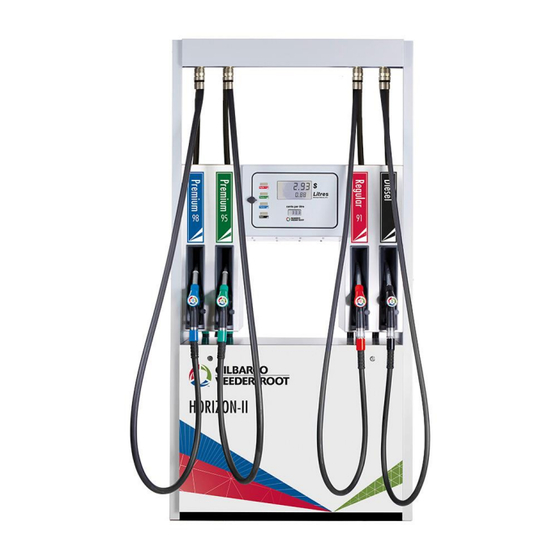
Page 13: Horizon-2
Horizon-2 • up to 4 products • Definition of dispenser sides: Remove the panels of the hydraulics for orientation. Dispenser side 1: the side where the filters are lo- cated Frontier • up to 2 products, accessible from both sides •... -
Page 14: Foundation
Installation of the Dispenser Before installation always consult the foundation dimensions of the respective dispenser type as this has de- tails of sumps, dimensions, and power requirements. Installation instructions for all additional devices must be available and followed. Before installing the dispenser, properly lay all necessary cables and pipes. If necessary, hoists must be used for heavy loads. -
Page 15: Requirements For Pressure Pump Operation
Requirements for pressure pump operation • device for the automatic interruption of the fuel flow to the dispenser in the case of a vehicle collision (e.g. Shear Valve) • check valve in the pressure line directly after the pump • submersible pumps, which are located within the respective storage tank and mounted such that the pump is below the liquid level •... -
Page 16: Opening The Dispenser Housing
Opening the dispenser housing Set the packed dispenser down at an appropriate place. Remove the packaging materials. Then remove the side panels as described below. Attention: Only open the dispenser with no electrical power connected! The panels are connected to the internal earthing system. Before removing the panels, disconnect the corresponding earth bonding conductors. -
Page 17: Placing The Dispenser On The Foundation
Placing the Dispenser on the foundation SK700-2 Lifting, with Forklift Lifting Bracket for use with Forklift is part number 140 870 491. Move the packaged dispenser using a forklift Mount the lifting bracket to the pump frame. truck to the island and set it down. Remove the The pump frame has specific holes for the packaging and the side panels from the pump, screws. - Page 18 Lifting with High point and straps Lifting Bracket Kit for use with High point. Note: • Lifting bracket, including spreader bar, is DN07630-450. • Suitable straps must be used, not part of lifting bracket kit. • Spreader bar must be positioned to not rub on CDM (use soft cloth) and only attached during lifting. Attention! When transporting the dispenser and placing it on the foundation there is a risk of injury from trapping.
- Page 19 HORIZON MK2 Lifting Procedure Lifting Bracket for use with Forklift is part number 140-993-422 Move the packaged dispenser using a folk-lift truck to Fit the lifting bracket to the forklift tines and position them centrally inside the pump the island and set down. Remove the packaging and front and rear panels from the pump, and then remove the bolts securing the pump to the wooden pallet.
- Page 20 Lifting, with Forklift Lifting Bracket Kit for use with High point. High Point Lift with straps Note: • Lifting bracket kit, including spreader bar, is DN07630-350. • Suitable straps must be used, not part of lifting bracket kit. • Spreader bar must be positioned above the top, as shown. DQ98014-001 •...
-
Page 21: Mounting The Dispenser On The Island (Part 1)
Mounting the dispenser on the island (part 1) Use the supplied bolts. The quantities given in the table below are the respective minimum number of bolts. More bolts can be used, but the function of the shear valves must be maintained. Attention: The mounting for LPG dispensers differs significantly. -
Page 22: Dispenser Overall Dimensions & Hydraulic Foot Prints
Dispenser Overall Dimensions & Hydraulic Foot Prints SK700-2 DQ98014-001 • Issue A Page 22 GVR Installation and Commissioning Manual... - Page 23 Overall Dimensions 5 Products, 10 Hose Suction or STP DQ98014-001 • Issue A Page 23 GVR Installation and Commissioning Manual...
- Page 24 HORIZON MK2 Overall Dimensions 1 Product, 2 Hose, Suction or STP DQ98014-001 • Issue A Page 24 GVR Installation and Commissioning Manual...
- Page 25 Overall Dimensions 2 Products, 4 Hose, Suction or STP DQ98014-001 • Issue A Page 25 GVR Installation and Commissioning Manual...
- Page 26 Overall Dimensions 3 Products, 6 Hose, Suction or STP DQ98014-001 • Issue A Page 26 GVR Installation and Commissioning Manual...
- Page 27 Overall Dimensions 3 Products, 6 Hose, Suction or STP DQ98014-001 • Issue A Page 27 GVR Installation and Commissioning Manual...
- Page 28 FRONTIER Overall Dimensions DQ98014-001 • Issue A Page 28 GVR Installation and Commissioning Manual...
- Page 29 Overall Dimensions DQ98014-001 • Issue A Page 29 GVR Installation and Commissioning Manual...
-
Page 30: Installation Cable Routing
ENDURA Overall Dimensions 1 Product, 2 Hose, Suction or STP 6.10 Installation cable routing 1) Cable 2) Cable feedthrough 3) Dispenser drip tray (Optional) 4) Cable duct DQ98014-001 • Issue A Page 30 GVR Installation and Commissioning Manual... -
Page 31: Typical Pipe Connection For A Pump
6.11 Typical Pipe connection for a Pump Pipe to suit the site. Modification may be required such as unique fitting in order to meet Pump installation. 6.12 Typical Pipe connection for a STP Pipe to suit the site. Modification may be required such as unique fitting in order to meet the STP installation. DQ98014-001 •... -
Page 32: Vapour Recovery Installation
6.13 Vapour Recovery Installation VR2 Installation Kit is provided for piping. Refer to the following diagram for the contents of the kit. A three-way ball valve is fitted under the dispenser so that during maintenance a Service Technician is pro- tected from expelled vapours from other in-service dispensers when VR pipe works may be disconnected. -
Page 33: Suction Line Installation
6.14 Suction line installation Attention: For delivery, the pump unit suction line connection is sealed with a plug. Remove it. To ensure the maximum flow rate, a separate 2" suction line must be used for each pump unit to connect to the supply tank. -
Page 34: Electrical Connection
6.16 Electrical connection Attention! Before opening the display housing or the hydraulic covers of the dispenser, switch off the power supply of the dispenser in the electrical distribution panel and secure the corresponding isolator against being switched on again. Before switching on the power supply of the dispenser, make sure that all junction boxes and housing parts are properly closed. -
Page 35: Separate Power And Data Cable Connections
6.17 Separate Power and Data Cable Connections Ensure that all the necessary electrical cables installed comply to the National standards. It is recommended that for any new installations that Steel Wire Armoured (SWA) Cables are used and that the Power (2.5mm²) and Data (1.5mm²) Cables are separated within two Conduits, in keeping with AS/NZS Electrical and Cabling rules, AS/NZS 3000:2018. - Page 36 JUNCTION BOX (ROSE) – 2 GLAND AND 3 GLAND DISPENSER Ensure that any Metal Glands are Earthed. POWER COMMS POWER COMMS 3 PHASE SUPPLY FOR STP & CRIND SINGLE PHASE SUPPLY FOR STP AND CRIND 400V-415V, 50Hz ± 2Hz 220V-240V, 50Hz ± 2Hz 220V-240V, 50Hz ±...
- Page 37 Ensure unused plastic cable glands are plugged with approved 12mm plug. Gilbarco 12mm plug. Part # 140-762-796 Gland with YELLOW DUST SEAL. This is not a Gas Seal. Remove existing Dust Seal & fit 12mm Plug & tighten securely. DQ98014-001 • Issue A Page 37 GVR Installation and Commissioning Manual...
-
Page 38: Final Work And Tests
6.18 Final work and tests ✓ Drip guard must be attached as described previously. ✓ Hydraulic lines must be leak-free. ✓ Ensure all Hose and Nozzle connections are tight before energising the Pump and testing with Fuel. Safe breaks (optional) must be fully connected. Junction box: ✓... -
Page 39: Preparing Work For Commissioning
Commissioning Preparing work for commissioning Attention! Before opening the display housing or the hydraulic covers of the dispenser, switch off the power supply of the dispenser in the electrical distribution panel and secure the corresponding isolator against being switched on again. Before switching on the power supply of the dispenser, make sure that all junction boxes and the display housing are properly closed. -
Page 40: Changing The Filter Elements
5) Fill the dispenser hydraulics with fuel as follows (Note the refuelling instruction) Attention! First open the lid of the filter bowl and fill the filter bowl and the suction line with fuel. Close the lid of the filter bowl. Note: The fuel dispensed when filling the hydraulics may contain test liquid residues and preservatives and is therefore not suitable for vehicles. - Page 41 Refuelling instruction Petrol & Diesel Attention! Observe the safety instructions at the beginning of this manual! 1) Switch off the engine and any auxiliary heating. Apply the hand brake. 2) Refuel only approved tanks/containers! 3) Lift the nozzle for the desired fuel out of the nozzle boot. The price per unit (PPU) is shown on the display.
-
Page 42: E-Cal Board
Meter calibration The dispenser is calibrated in the factory prior to delivery. Check on site the measuring accuracy of all meters and recalibrate if necessary. Only one calibration switch may be opened at any one time for calibration. The calibration switch assignment can be called up via parameter 76.3 (see description later in this document). -
Page 43: Meter - Hose Assignment
Meter - hose assignment In dispensers with cord retract, the meter is located on the opposite side of the dispenser to the corresponding nozzle. 1) Dispenser without cord retract (OR) 2) Dispenser with cord retract (CR) 3) Meter Parameter 76.1: Calibration refuelling The Manager Keypad is on the inside of the display housing. -
Page 44: Parameter 76.2: Read And/Or Write Calibration Factor
4) After the delivery process, remount the nozzle into the nozzle boot. Then zeroes start flashing in the volume display. Amount Volume 5) Read off the actual delivered volume from the prover can and enter the value with three decimal places (example 20.000 litres actual delivered volume) Amount Volume... -
Page 45: Parameter 76.3: Calibration Switch Assignment
Parameter 76.3: Calibration switch assignment Amount Volume state display meter E-Cal Board number 1) Enter the parameters (CC 76 and FC 3). Lift any nozzle. Now you can see, which meter numbers are assigned to the hoses and if the corresponding calibration switches are open or closed (state display E-Cal Board - Switch: 0 = closed, 1= open). -
Page 46: Overview Vapour Recovery Systems
Vapour recovery 10.1 Overview vapour recovery systems MEX 0544 pump: • constant speed pump • recovery rate control by solenoid valves 1) Vapour recovery lines to the individual hoses. The arrows indicate the vapour flow direction. 2) Coax hose 3) Vapour recovery controller 4) Solenoid valves 5) Motor with vapour recovery pumps 6) Insulating piece... -
Page 47: Vapour Recovery Adjustment
10.3 Vapour recovery adjustment The vapour recovery system is tested prior to delivery and must be adjusted once the dispenser is installed on site. Unless local regulations specifically require a “wet test”, carry out an auto adjustment with the FB1 service terminal using the dry test method (without fuel delivery) according to EN 16321-2. - Page 48 Programming Codes and Modes of Operation Set Pump Numbers Level 2 – Command Code 40 Security Code: 1503 (for level 2 programming) Command code 40 is entered in level two programming to access 2-Wire parameters. The layout and digit position meaning for this programming feature is shown below. Func- tion Code...
- Page 49 The example below assigns pump side B address 8. Keypad: 40– set 2-Wire command Volume Keypad: ENTER Volume Keypad: ENTER– set Pump ID number Volume Keypad: 2 – select side B Volume Keypad: ENTER Volume Keypad: 8 – enter address 8 Volume Keypad: ENTER Volume...
- Page 50 Set Mode of Operation Level 1 – Command Code 24 Security Code: 2222 (for level 1 programming) Command code 24 is entered in level one programming to set the dispenser operating mode. The operation mode setting determines how the dispenser is controlled remotely or if it operates in Stand Alone mode.
- Page 51 Keypad: 2 – select Standalone mode olume Keypad: ENTER – Accept olume The F1 key will allow additional programming or the F2 key may be used to exit programming. Note: 1. To set to operate in Self-Serve mode with 2-Wire communications using either Corporate (USA), Australian Protocol 1 or Australian Protocol 2, the above action step that selected “2”...
-
Page 52: Before Starting Work
Maintenance instructions 12.1 Before starting work For certain maintenance work it is required to restrict public access to the dispenser and/or isolate the dispenser from the electrical power supply. In the maintenance tables below these respective necessary safety measures are marked with following symbols: Isolate dispenser from electrical power supply Restrict public access to the dispenser 12.2 Checks and actions to be carried out by the station operator... - Page 53 Reference 1 - Cleaning Clean your dispenser at regular intervals (recommended: weekly), but immediately in case of considerable contamination by fuel or other aggressive media to ensure the qualitative appearance and corrosion protection. Attention: Never use fuel, thinners or strong alkaline cleaning agents, but only cleaners approved by GVR. Never use abrasive cleaning aids such as steel wool or wire brushes, but only damp cotton or leather cloths.
-
Page 54: Checks And Actions By Service Technicians
12.3 Checks and actions by service technicians X = required Interval (in years) Equipment Checks and actions Hoses incl. Check electrical resistance between nozzle outlet nozzles pipes and equipotential bonding (R<1MOhm) Nozzles Check minimum switch off and ball-tilt safety device Check measuring accuracy, calibrate the meter if Meter necessary... -
Page 55: Further Instructions For The Service Technician
Troubleshooting If the refuelling process is interrupted or if the dispenser does not start, proceed as follows: • Check the power supply. • Check, if the dispenser is connected and authorised by the forecourt controller. • If an error code is shown on the dispenser display, note the code and consult a service technician (The error code list can be requested from Gilbarco). -
Page 56: Transport
Transport, storage, disposal 14.1 Transport You can request from Gilbarco transport recommendations for the delivery of dispensers. These recommen- dations serve to avoid damage when transporting the dispensers and gives for example instructions for cor- rect packaging and load securing during transport. 14.2 Storage conditions Gilbarco recommends the following storage conditions for dispensers: Min. -
Page 57: Operation Conditions
Technical data 15.1 Operation conditions l/min Maximum flow rate 40; 70; 120* l/min Minimum flow rate 4; 4; 8 liter Minimum measured quantity 5; 5; 10 Maximum permissible ±0,5 measurement error Accuracy class Viscosity 0,4–17 mPa.s Maximum system pressure Minimum system pressure Ambient temperature range -40 to +55** ºC... -
Page 58: Dispenser Dimensions
15.3 Dispenser dimensions Weight (kg) Length (mm) Width (mm) Height (mm) 290 – 780 1970 – 2170 SK700-2 1033 - 3075 1715 – 2540 Horizon-2 1200 2390 190 – 250 1520 – 2330 Frontier 135 – 215 1400 – 1820 Endura 15.4 Hose reach Measuring principle... -
Page 59: Power Consumption
15.5 Power consumption Max. current (Amps) 2 or more 1 fuel High flow fuel module module(s) modules 1-Phase Motor 230 V 12,5 Suction Pump 3-Phase Motor 230 V 10,5 14,0 3-Phase Motor 400 V 1-Phase Motor STP with Vapour Recovery 3-Phase Motor Electronics (Calculator) max. -
Page 60: Dispenser Nameplate
The contents of these instructions must not be copied in whole or in part without the permission of Gilbarco. Gilbarco reserves the right to change textual or pictorial content without special notification. 16.3 Contact Details Gilbarco Veeder-Root ANZ, Switchyard, Warehouse 5, Building 2 161 Manchester Rd, Auburn NSW 2144 Tel.: 1300 131 867...
Need help?
Do you have a question about the SK700-2 Series and is the answer not in the manual?
Questions and answers